EasyManua.ls Logo

SABROE SAB 193 S User Manual

SABROE SAB 193 S
177 pages
To Next Page IconTo Next Page
Page #1 background imageLoading...
Page #1 background image
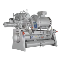
SAB 193-233-283 S A-frame (including ATEX)
Screw compressor units
Engineering manual EN

Table of Contents

Questions and Answers:

SABROE SAB 193 S Specifications

General IconGeneral
ModelSAB 193 S
Cylinder Quantity3
RefrigerantR717 (Ammonia)
Frequency50 Hz / 60 Hz
Cooling CapacityVaries with refrigerant and operating conditions (consult selection guide)
Motor PowerVaries with operating conditions (consult selection guide)

Summary

1. Introduction

1.1 Purpose

Provides data for sales and planning phases, including component descriptions and technical functions.

1.2 Main users

Manual intended for sales, service, and contracting; warranty work by competent personnel only.

1.3 Compressor name, Sabroe/Frick

Explains the naming convention for Sabroe and Frick compressors and their correspondence.

1.4 Amendments to the manual

Lists revisions and updates made to the manual across different versions.

2. Signs and warnings

2.3 Compressor name plate

Details the information found on the compressor name plate and serial number structure.

2.4 Compressor name plate - ATEX

Specifies the information on the name plate for ATEX certified compressors.

2.5 Labelling of explosion-proof equipment

Explains ATEX directives, material groups, categories, hazardous environments, and temperature classes.

2.7 Unit/pipe system name plate

Describes the information on the name plate for the unit and piping system.

2.8 Signs

Illustrates and explains various safety signs found on the equipment.

3. Safety precautions

3.1 Areas of application

Defines permissible applications and restrictions for the screw compressor unit.

3.1.1 Application of the screw compressor

Specifies how the compressor should and should not be used to prevent damage or injury.

3.2 Safety precautions

General safety measures including work area, operation, and maintenance precautions.

3.2.1 General precautions

General safety guidelines to supplement other manuals and regulations.

3.2.4 Safety during maintenance and service

Precautions for safe maintenance and service activities on the compressor.

3.2.5 Electrical installations

Safety considerations for electrical installations, particularly for ATEX executions.

3.2.7 Lubricating oils

Details on types of compressor oils and safety guidelines for handling them.

3.2.10 F-gas regulation (fluorinated greenhouse gases)

Information on F-gas regulation requirements, including bans, labelling, and leakage tests.

3.2.11 First aid for accidents with ammonia

Provides first aid measures for ammonia exposure, including inhalation, eyes, and skin contact.

3.2.12 First aid for accidents with HFC/HCFC

Gives first aid instructions for accidents involving HFC/HCFC refrigerants.

4. Technical description

4.1 Description of the screw compressor

Details the design and construction of the screw compressor unit and its main components.

4.3 Description of main components and systems

Overview of major subsystems within the screw compressor unit.

4.4 Control system

Describes the UniSAB III control and monitoring system for compressor operation.

4.5 Compressor

Details the compressor itself, including the integral suction strainer.

4.6 Variable speed drive (VSD)

Discusses VSD equipment, its integration, and potential vibration issues.

4.7 Compressor lubrication system

Explains the functions and types of the compressor lubrication system.

4.12 Compressor oil separation system

Details the oil flooded screw compressor and the oil separation system.

4.13 Automatic oil return valve

Describes the function of the automatic oil return valve (EVRB).

4.14 External oil filter

Explains the external oil filter, its construction, and protection mechanism.

4.16 Compressor hydraulic system

Details the hydraulic system for moving the slide valve and slide stop.

4.17 Compressor oil cooling systems

Describes different systems for controlling compressor oil temperature.

4.18 Suction check valve by-pass

Explains the function and installation of the suction check valve with by-pass.

4.19 Requirements for ambient temperatures and humidity

Specifies operating limits for ambient temperature and humidity.

4.21 Selecting lubricating oil for Sabroe screw compressors

Guidance on selecting the correct lubricating oil for Sabroe screw compressors.

4.23 Heating rod element for oil heating, pos. 30

Describes the heating rod element for maintaining oil temperature during standstill.

4.25 Cold-start system

Details the 'cold-start' discharge valve for rapid oil pressure development at start-up.

4.26 Compressor protecting system, pos. 220 and 221

Explains the protecting system for preventing inadmissible high pressure.

4.27 Oil cooling system and general piping layout

Overview of oil cooling systems and their general piping layout.

4.29 Thermosyphon oil cooling

Describes the operation and piping arrangement for thermosyphon oil cooling systems.

4.31 Connection to AlfaNova oil cooler

Details maximum permitted connection forces and moments for AlfaNova oil coolers.

4.32 KRACHT oil pump

Describes the KRACHT oil pump, its features, and by-pass valve functions.

4.33 Economiser, high-stage (optional)

Explains the economiser option for increased system capacity and efficiency.

4.34 General piping diagram

Presents the general piping diagram for the compressor unit.

4.35 Key to piping diagram

Provides a key to valve positions during operation for piping diagrams.

4.36 Instrumentation

Details the sensors, valves, and components connected to the UniSAB III control system.

5. Physical and connection data

5.1 Physical data

Provides dimension sketches and tables for equipment data.

5.2 Allowable flange loads

Lists allowable axial, vertical, and lateral loads and torques for flange connections.

5.3 Mounting of suction isolation valve

Instructions on the correct placement and recommended distance for the suction isolation valve.

5.4 Connection data

Details connection dimensions and port locations for the compressor unit.

5.4.1 Connections to compressor unit

Provides dimensional outlines and connection details for compressor models.

5.4.2 Electrical connections

Shows the positions of electrical connections and components on the unit.

5.4.3 List of components

Lists and describes various components and their connections, including motor data.

6. Technical data

6.1 Data for compressor units

Provides unit dimension data and external heat surface areas.

6.2 Other data

Includes electric motor weights and geometrical swept volume data.

6.3 Planning the machine room

Guidance on planning sufficient space around the plant for maintenance.

6.4 Minimum compressor flow at 3550 rpm

Lists minimum suction flow capacities for different compressor models.

6.5 Operating limits

Example of permissible working range for a compressor based on temperatures.

6.6 Selecting electric motor

Guidelines for selecting appropriate IEC electric motor types for compressors.

6.7 Motor dimension

Factors to consider when determining motor size based on power demands.

6.8 Motor selection and starting torque

Details motor sizing for operating conditions and starting torque requirements.

6.10 Direction of rotation

Specifies the correct clockwise rotation direction for the compressor.

6.11 Emergency stop

Describes the requirements for an emergency stop system integrated with UniSAB III.

6.13 Noise data

Information on noise data measurement standards (SWL, SPL) and calculation.

6.14 Noise data for SAB 193-233-283

Provides specific noise data (SWL, SPL) for SAB 193-233-283 compressors.

6.15 Vibrations and test pressure levels

Covers vibration data standards and test pressure levels for compressors.

6.15.1 Vibration data for compressors (all compressor types)

Details vibration data standards and limits for reciprocating and screw compressors.

6.15.2 Test pressure levels for standard compressors and components

Specifies standard pressure test levels for compressors and components.

7. Installation instructions

7.1 Installation

Describes dangers and safe installation methods for the equipment.

7.2 Safety precautions

Emphasizes reading safety precautions before installation to prevent injury or damage.

7.4 Installation and first start-up procedure

Details mechanical, electrical, and safety equipment installation requirements.

7.6 Personnel requirements

Specifies that installation personnel must be competent and well-trained.

7.9 Safety equipment

Lists essential safety equipment to be used during installation.

7.13 Lifting and loading instructions

Refers to transport instructions for safe lifting and loading procedures.

7.17 Alignment of compressor and unit

Explains the importance of proper alignment for service life and vibration reduction.

7.19 Alignment of compressor and motor

Provides a method for achieving parallel shaft alignment between compressor and motor.

7.21 Mounting directly on the foundation

Details the process of mounting the unit directly onto a concrete foundation.

7.23 Damping using vibration dampers

Describes the use of vibration dampers for efficient damping of vibrations.

7.24 VSD equipment

Addresses VSD equipment and the assessment of feasibility for variable speed operation.

7.25 Calculation of centre of gravity, support reactions and tipping angle

Provides a method for calculating center of gravity, support reactions, and tipping angle.

7.26 Instruction for mounting of coupling

Instructions for mounting and dismantling the coupling between motor and compressor.

7.27 BPU coupling installation procedure

Step-by-step procedure for the installation of the BPU coupling.

7.28 Piping connections

Guidance on laying pipes to avoid stress from temperature changes.

7.29 Connecting electricity supply

Safety precautions and instructions for connecting the electricity supply.

7.30 Pressure testing

Procedures for pressure testing the refrigeration plant and unit.

7.31 Evacuation of the refrigeration plant

Instructions for evacuating the plant to remove air and moisture.

7.32 Oil charging

Procedure for charging the compressor unit with lubricating oil.

7.33 Final installation check

A checklist for verifying the completeness and correctness of the installation.

8. Components

8.1 UniSAB III

Describes the UniSAB III control system and its sensors.

9. Settings

9.1 Control system

Refers to the UniSAB III Operating manual for control system descriptions and settings.

10. Operating instructions

11. Maintenance instructions

11.1 Safety precautions

Emphasizes reading safety precautions before performing maintenance.

11.2 Maintenance of compressor unit

Outlines the maintenance schedule including daily, periodic, and major overhaul tasks.

11.3 Stopping routine

Describes procedures for stopping and starting the compressor for short and long standstills.

11.4 Long-term storage

Provides guidelines for long-term storage of equipment to prevent deterioration.

11.5 Visual inspection

Details visual checks for oil pressure, oil level, noise, and vibration.

11.7 General rules for use of lubricating oil in refrigeration compressors

Rules for using lubricating oil, including charging, grade, and mixing.

11.8 Assessing the oil

Explains the importance of oil in the compressor and recommends oil analysis.

11.9 Visual assessment

Describes how to visually assess oil quality for clarity, particles, and feel.

11.10 Analytical evaluation

Details the process and benefits of oil analysis by the supplying company.

11.12 Charging compressor with lubricating oil

Provides a step-by-step procedure for charging the compressor with oil.

11.13 Oil charge

Guides on calculating the necessary oil amount based on unit composition and tables.

11.14 Motor

Briefly covers motor lubrication and replacing motor bearings.

12. Faultfinding instructions

12.1 How to carry out faultfinding

Explains the situations requiring faultfinding and emphasizes systematic approaches.

12.2 Troubleshooting

Provides tables for common problems in refrigeration plants and compressor units.

13. Service instructions

14. Transport instructions

14.1 Safety precautions

Highlights dangers and safety precautions related to equipment transport.

14.4 Handling of compressor and unit

Details on handling the compressor unit, including lifting points and weight.

14.5 Loading instructions

Provides critical warnings and instructions for safe unit loading onto transport.

14.12 Storage

Guidelines for storing the unit to prevent damage and corrosion.

15. Commissioning instructions

15.1 Safety precautions

Emphasizes safety precautions and reading associated documentation before commissioning.

15.2 Preparations for commissioning

Covers final installation checks, personnel requirements, and training.

15.4 Evacuation and charging of refrigerant

Details procedures for plant evacuation and refrigerant charging.

15.5 Start-up

Instructions for plant start-up, including alignment checks and fuse management.

15.7 Checklist for commissioning

A comprehensive checklist for commissioning compressors, chillers, and heat pumps.

16. Spare parts list

16.1 Please see separate spare parts manual

Directs users to a separate manual for spare parts information.

17. Spare parts drawings

17.1 Please see separate spare parts manual

Indicates that spare parts drawings are available in a separate manual.

18. Final disposal

18.1 Safety precautions

Safety measures to be followed before and during dismantling of the plant.

18.2 Waste disposal

Guidelines for the proper disposal of machine parts, oil, refrigerant, and electric components.

19. Appendices

Related product manuals