Before leaving the factory, your unit was carefully
inspected for physical imperfections as a routine part of
our systematic quality control to ensure a flawless
appearance.
After the pre-amplifier has been unpacked, inspect it
for physical damage.
Save the shipping carton and all packaging materials,
as they were carefully designed to reduce to a minimum
the possibility of transportation damage.
In the unlikely event that damage has occurred,
immediately notify your dealer and request the name of
the carrier so that a written claim to cover the damages
can be initiated.
THE RIGHT
TO
ANY CLAIM AGAINST A PUBLIC
CARRIER CAN BE FORFEITED IF THE CARRIER IS NOT
NOTIFIED PROMPTLY, AND IF THE SHIPPING
CARTON AND PACKING MATERIALS ARE NOT
AVAILABLE FOR INSPECTION BY
THE
CARRIER.
SAVE ALL PACKING MATERIALS UNTIL THE CLAIM
HAS BEEN SETTLED.
Adequate ventilation will extend the trouble free life
of your pre-amplifier.
The 3000 may be mounted either horizontally or vertically.
However,
it
should not be totally enclosed with other heat
producing components.
The cut-out for custom panel mounting is 5 in. high
by 17.5 in. wide. Allow enough space around the opening
to clear adjacent panel-mounted components. The outside
dimensions of the front panel are 5.25 in. by
19
in. If your
cabinet has doors or a lid, the mounting panel should be a
minimum of .75 in. behind the doors or lid when closed
to clear knobs and switches. The mounting holes on the
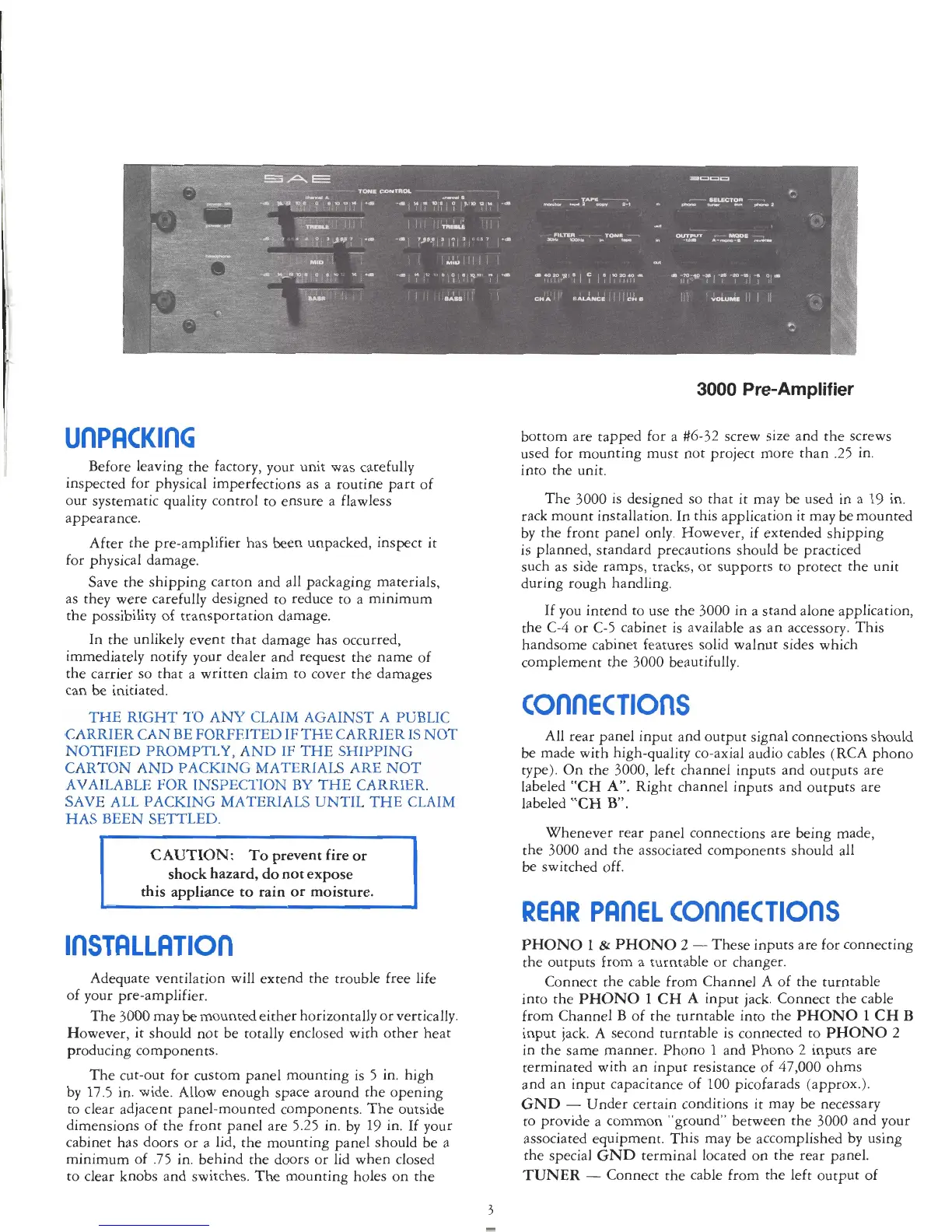
3000
Pre-Amplif ier
bottom are tapped for a #6-32 screw size and the screws
used for mounting must not project more than
.25
in.
into the unit.
The 3000 is designed so that it may be used in
a
19
in.
rack mount installation. In this application it may be mounted
by the front panel only. However, if extended shipping
is planned, standard precautions should be practiced
such as side ramps, tracks, or supports to protect the unit
during rough handling.
If you intend to use the 3000 in a stand alone application,
the C-4 or C-5 cabinet is available as an accessory. This
handsome cabinet features solid walnut sides which
complement the 3000 beautifully.
All rear panel input and output signal connections should
be made with high-quality co-axial audio cables (RCA phono
type).
On the 3000, left channel inputs and outputs are
labeled "CH
A".
Right channel inputs and outputs are
labeled
"CH
B".
Whenever rear panel connections are being made,
the 3000 and the associated components should all
be switched off.
REAR
PAnEL
COflnECTIOnS
PHONO
1
&
PHONO
2
-
These inputs are for connecting
the outputs from a turntable or changer.
Connect the cable from Channel A of the turntable
into the PHONO
1
CH
A
input jack. Connect the cable
from Channel B of the turntable into the PHONO
1
CH
B
input jack. A second turntable is connected to PHONO
2
in the same manner. Phono
1
and Phono
2
inputs are
terminated with an input resistance of 47,000 ohms
and an input capacitance of
100
picofarads (approx.).
GND
-
Under certain conditions it may be necessary
to provide a common "ground" between the 3000 and your
associated equipment. This may be accomplished by using
the special GND terminal located on the rear panel.
TUNER
-
Connect the cable from the left output of