English
12
10 - MB7P CABINET - INSTALLATION AND USE
• The M.B.7P cabinet allows a greater autonomy and
increases the supply interval.
• Remove the cabinet from its packing as well as all parts
contained in the inside of the cabinet.
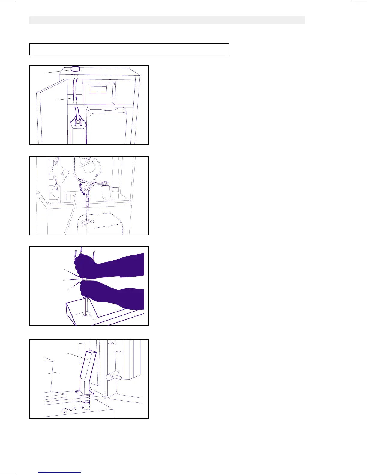
• Position the drain adapter (40) on the cabinet top and
connect it to the drain hose (41)(Fig.P).
• Set the free end into the drain tank.
• Position the machine onto the cabinet and remove the rear
cover unscrewing the eight fixing screws.
• Remove the water tank.
• Disconnect the silicone tube which connect the tank valve to
the filter.
• Unscrew the screws which fix the valve. Remove the valve
in order to avoid possible water leakages by accidentaly
inserting the water tank.
• Connect the water tank hose found in the inside of the
cabinet , to the filter and route it through the machine water
supply access hole located in the bottom of the unit. (Fig.R).
• Let the hose pass into the hole of the 20 liter tank cap, once
it has been filled with fresh water.
•
Remove the punch-out plug from the drip tray (Fig. S), check
that the hole aligns with the drain adapter. If this is not the
case, move the machine and make them align.
• Insert the dump box adapter (42) into the hole located in
the bottom of the unit making sure that the holes coincide
(Fig.T).
• Insert the coin box adapter (43) into the proper holes and
fix it with screws, washers and nuts (Fig.T).
• Insert the pin into the coin box transversal hole in order to
avoid that the machine can be lifted from the cabinet(Fig.T).
• Water filling:
• Open the front door panel and override the front door
panel sensor switch by inserting the “orange key” (7) and
switch the machine on with the main switch.
• Hold down the rinse switch (8) until water regularly flows
out from the dispenser lines. (29).
• Take away the “orange key “ (7) and close the door.
Fig. R
43
42
Fig. T
Fig. S
40
41
Fig. P




 To Next Page