Do you have a question about the SAF MIG 400 BL and is the answer not in the manual?
Electrical safety, connection, maintenance, troubleshooting.
Connecting to the mains, checking supply, plugs, earth connection.
Workstation safety, isolation, grounding, tool handling.
Internal checks, isolation, HV/HF circuit caution, periodic checks.
Ventilation, fume extraction, gas concentration limits.
Eye protection from arc glare, UV radiation, filter grades.
Noise emission levels, hearing protection, noise limit compliance.
Fire prevention, keeping flammable items away, fire extinguisher.
General gas safety, risks, storage, piping, equipment use.
General gas safety, risks, storage, piping, equipment use.
Personal protective equipment, maintenance, cooling liquid safety.
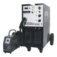
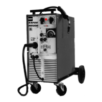
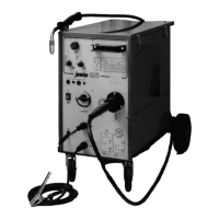
Description of the MIG-MAG welding installation.
Components of the welding set (power supply, reel, cable, etc.).
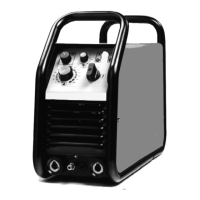
Description of the front panel controls and indicators.
Optional equipment like measuring instruments, polarity inversion.
Primary voltage, current consumption, power, cable specifications.
No-load voltage, adjustment range, duty cycle, welding cycle, protection.
Plate type, wire speed, wire diameter, torch connection.
Physical dimensions and weight of the power source and wire feed unit.
Instructions for unpacking the welding set from its packaging.
Connecting the power source to the mains power supply.
Equipping the wire feed unit and torch for intended use.
Connecting the gas cylinder and hose to the generator.
Steps to power on the unit, check indicator lamps, prepare for welding.
Explanation of different welding cycles (2-stroke, 4-stroke, spot).
Table of welding positions, wire diameters, thicknesses, settings.
Table of no-load voltages for different switch positions and settings.
Periodic checks, cleaning, safety precautions for maintenance.
Maintenance of the wire feed unit's vertical plate and cleaning.
Maintenance of wire feed rollers and guides, motor reducer.
Torch maintenance, connection checks, spatter removal, consumables.
List of replacement parts for the front panel, wire feeder, and internal components.
Table of common power-on problems and their solutions.
Table of issues related to trigger operation (no wire, no gas, no current).
Troubleshooting steps for incorrect no-load voltages.
| Welding Process | MIG/MAG |
|---|---|
| Input Voltage | 3 x 400 V |
| Welding Current Range | 30 - 400 A |
| Protection Class | IP23 |
| Duty Cycle | 60% @ 400 A |