XP Transponders User Guide Rev 1.3
Use an antenna designed to be used with aviation transponders with the characteristics documented in
Table 3.
Table 3 – Transponder Antenna Requirements
<1.5 between 1030 to 1090 MHz
The gain must not be less than the gain of a matched quarter-
wave stub minus 3 dB over 90 percent of a coverage volume
from 0 to 360 degrees in azimuth and from 5 to 30 degrees
above the ground plane when installed at the center of 1.2 m
(4 foot) diameter (or larger) flat circular ground plane.
Underside of aircraft fuselage, nominally at the wing root
Note: If your installation does not meet all of the above requirements, transponder
performance (range) may be hindered and damage to the transponder could result.
Important:
Whenever power is supplied to the transponder, a 50 ohm load should be provided
to the SMA connection. Ensure that the antenna selected provides a 50 ohm
termination for the transponder.
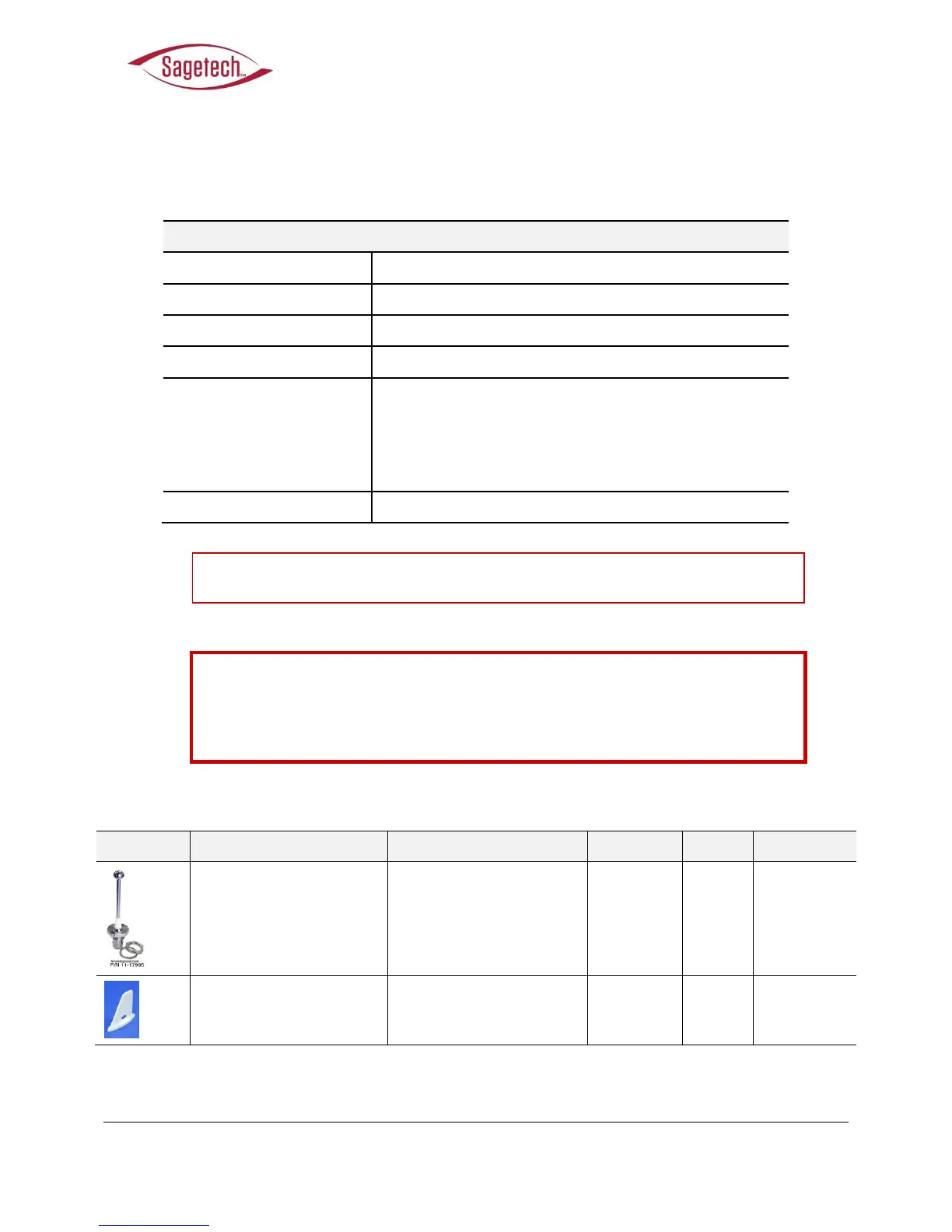
Table 4 – Examples of Transponder Antennas
Aircraft Spruce and Specialty
Aircraft Spruce and Specialty