Do you have a question about the SainSmart Genmitsu CNC and is the answer not in the manual?
Detailed dimensions for XZ axis components, including height and width measurements.
Specifications for corner connectors and support bases, including screw sizes and base dimensions.
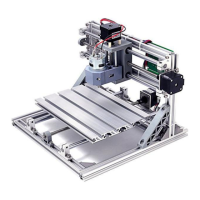
Assembly instructions for the main base frame, detailing aluminum extrusion lengths and fasteners.
Steps for constructing the top frame section of the CNC router.
Installation of corner pieces, spacers, and connectors to strengthen the frame structure.
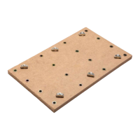
Front view illustration showing dimensions for the axis support base.
Side view illustration detailing the dimensions of the axis support base.
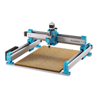
Guide for installing Y-axis components like sliders and the mesa.
Procedure for mounting stepper motors onto the X and Y axes.
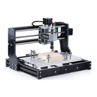
Instructions for installing the XZ axis assembly onto the main frame.
Diagram showing the assembly of the X-axis lead screw, copper nut, and spring.
Schematic detailing the Y-axis lead screw, nut seat, copper nut, and spring assembly.
Steps for assembling the motor coupling to the lead screw using set screws.
Guidance on installing bearings for smooth movement of the CNC axes.
Process for mounting the main control board onto the router frame.
Comprehensive wiring diagram for connecting GRBL board, motors, spindle, and power.
| Frame Material | Aluminum |
|---|---|
| Connectivity | USB |
| Spindle | 775 spindle motor (12-36V DC) |
| Controller | GRBL |
| Software | Candle (GRBL controller) |
| Supported OS | Windows, Linux |
| Supported File Formats | G-code |
| Supported Materials | Wood, plastic, acrylic, PCB |
| Z-axis Travel | 45 mm (1.77 in) |