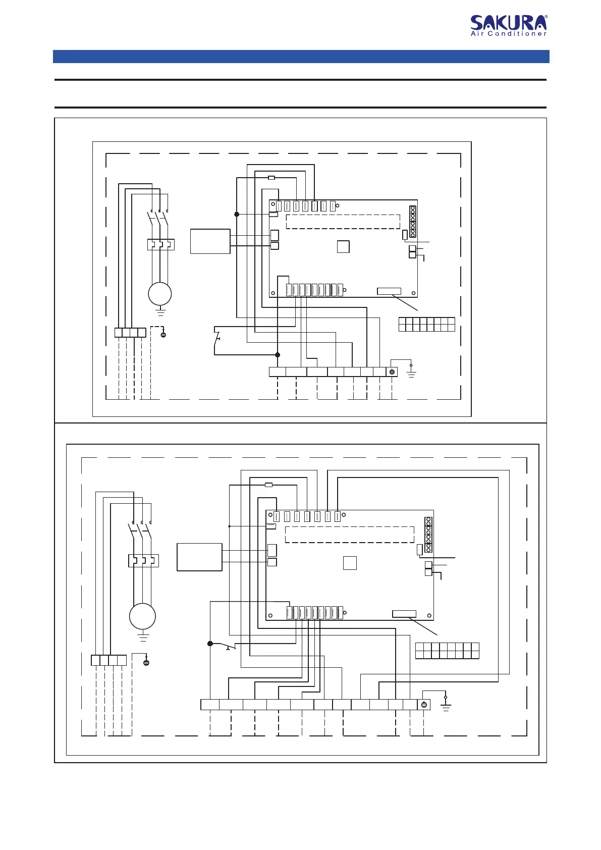
Wiring Diagram
PE
YLW/GRN
N
comp1
L
comp2
LP1/HP1
Dip Switch
FM
T
R
S
KM
FR
N
PE
Connect To Outdoor
KM
YLW/GRN
LP2/HP2
RED
BLUE
BLUE
YELLOW
RED
YLW
WHT
WHT
YLW
Note: KM - AC Contactor FR - Thermal Relay-------------- Installation Connection
To Power Supply 380-415V/3Ph/50Hz
COM
Dip Switch Setting
1
2
3
4
5 6 7
8
0
0
0
0
0
0 0
0
Note: 0 - OFF, 1 - ON
RED
FR
Switching
Power Supply
Board (SMPS)
Inner Coil
Temperature
Sensor (Copper)
Indoor Temperature
Sensor
Connect To Wallpad
(4 Core Wires)
BMS Connection
On Port
A12
A11
Indoor Blower
Compressor 1
Compressor 2
Relays
I.C
Live1
Live2
D01
D02
D03
D04
D05
N
COMP 2
D11
D12
D13
D14
D15
D16
D17
D18
PE
YLW/GRN
N
comp1
L
comp2
LP3/HP3
FM
T
R
S
KM
FR
N
PE
Connect To Outdoor
To Power Supply 380-415V/3Ph/50Hz
KM
YLW/GRN
LP4/HP4LP2/HP2LP1/HP1
comp3 comp4
RED
BLUE
BLUE
YELLOW
RED
YLW
YLW
YLW
YLW
WHT
WHT
WHT
WHT
Note:KM - AC Contactor FR - Thermal Relay --------------- Installation Connection
COM
Dip Switch Setting
1 2
3
4
5
6 7 8
1
1
0
0
0
0 0
0
Note: 0 - OFF, 1 - ON
RED
FR
Switching
Power Supply
Board (SMPS)
Indoor Blower
Compressor 1
Compressor 2
Compressor 3
Compressor 4
Relays
I.C
Live1
Live2
D01
D02
D03
D04
D05
N
COMP 2
D11
D12
D13
D14
D15
D16
D17
D18
Inner Coil
Temperature
Sensor (Copper)
Indoor Temperature
Sensor
Connect To Wallpad
(4 Core Wires)
BMS Connection
On Port
A12
A11
Dip Switch
PCB
PCB
Model : FASN400 / 500 / 600 (With Control PCB)
Model : FASN200 / 250 / 300 (With Control PCB)
Sakura Air-cooled Split Ducted Air Conditioner
 Loading...