4
Note:
Field of View: Make sure that the target is larger than the unit’s spot size. The smaller the target, the closer you should be
to it. When accuracy is critical, make sure the target is at least twice as large as the spot size.
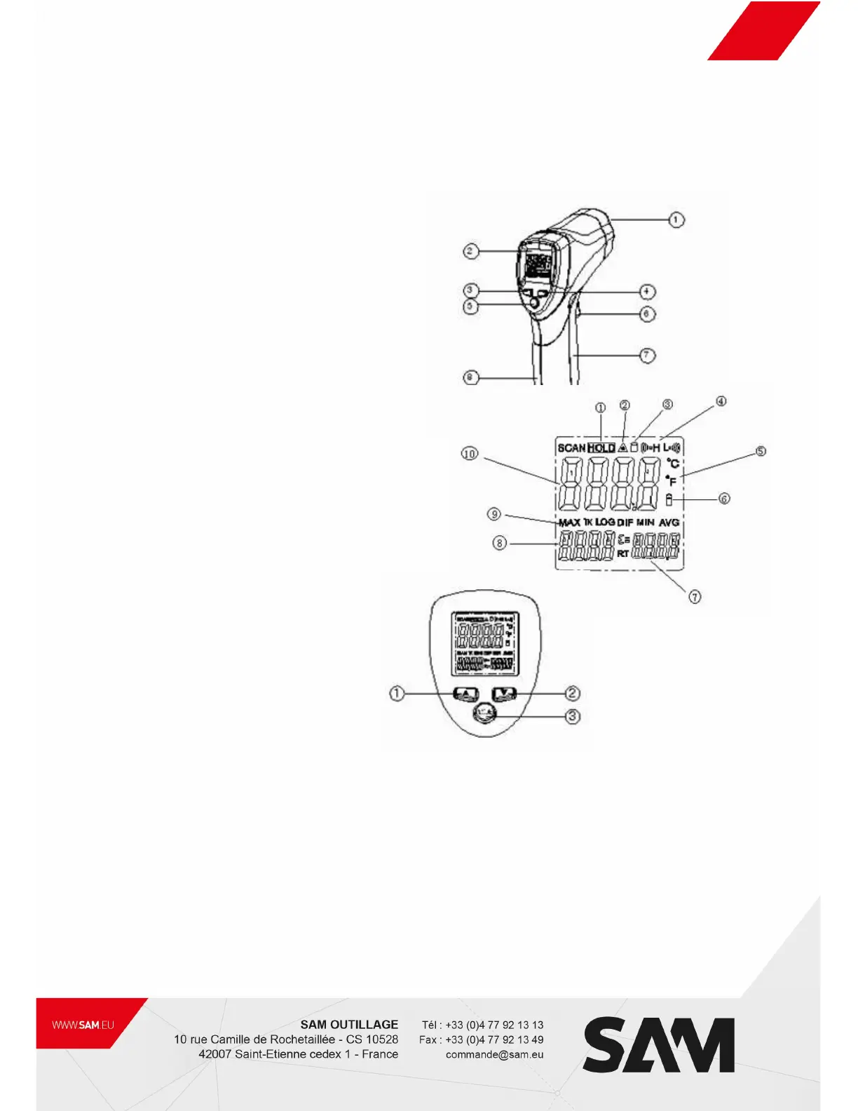
2. FRONT PANEL DESCRIPTION
① IR sensor
② LCD Display Laser pointer beam
③ up button
④ down button
⑤ mode button
⑥ Measurement Trigger
⑦ Battery Cover
⑧ Handle Grip
3. INDICATOR
① Data hold
② Laser ” on” symbols
③ Lock symbol
④ High alarm and low alarm symbol
⑤ °C /°F symbol
⑥ Low power symbols
⑦ Emissivity symbol and value
⑧ Temperature values for the MAX
⑨ Symbols for MAX
⑩ Current temperature value
4. Buttons
① Up button (for EMS,HAL,LAL)
② Down button (for EMS,HAL,LAL)
③ MODE button
(for cycling through the mode loop)
Functional Design
1. the switches of C/F sat in a cell switching
2. In the measuring time up, down keys to adjust the Emissivity.
3. In the hold time, up keys to turn on or off the laser
Down keys to turn on or off the backlight
4. To set values for the High Alarm (HAL), Low Alarm (LAL) and Emissivity (EMS), press the MODE button until the appropriate
code appears in the display, press the UP and down buttons to adjust the desired values.