23
The following Figs. 2, 2-1 and table indicate how to de-
termine the length of the drawpipe.
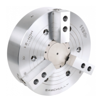
3-1 Manufacture of drawpipe
Mounting of Drawpipe
Thread
L
b c
d
a
e min.
f Max.
12
Note) Total draw bar is designed to 3-4mm longer length as consider-
ing tolerance.
Insecure threads will cause the drawpipe to vibrate.
With the thickness of drawtube minimized, thread
part ‘e’ to the aximum permissible thread dia. For
tube strength, use the material of tensile strength
of 3.8Mpa (38kg/mm) or more. Concentricity of a
and d to f should be reduced by 0.05mm. (Fig.2)
The ‘L’ dimension can be found by the above table
when the distance A between the cylinder adaptor and
the back plate is given see Fig.2-1.
ex) When the distance A is 800mm with chuck MH-206
combined with cylinder SD-15452 the total length
of the draw pipe is L=A+41=800+41=841Thread the
part ‘a’ to JIS standard 6H, 6h, 6g,corresponding to
the thread of cylinder piston rod.
Secure strength of drawpipe. The gripping force is
lost if the chuck is broken because of insufficient
strength. As a result, the work piece discharges,
there by causing danger. Insecure threads will
cause the drawbar to vibrate. Thread c, e should be
concentric within 0.05mm T.I.R. (Fig.2)
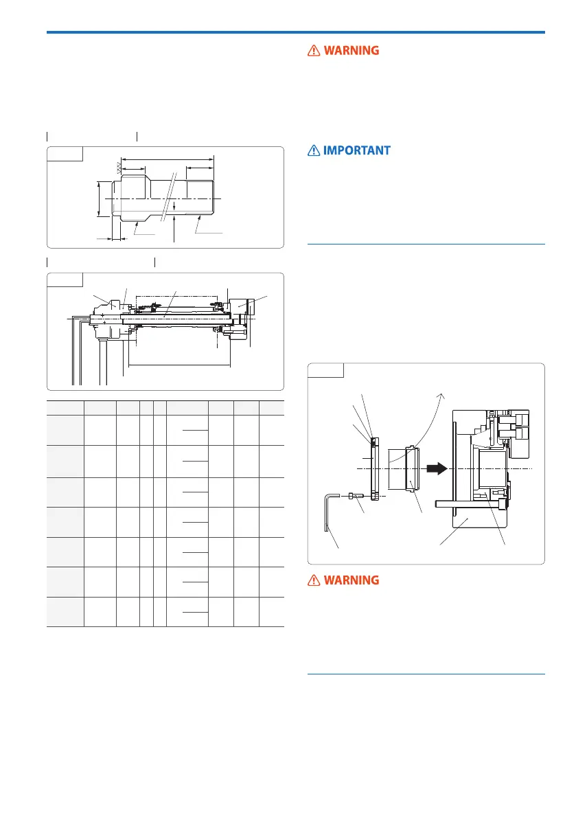
Remove 6 bolts with a hexagon wrench to remove the
plunger nut with the drawnut. Next, loosen the hexa-
gon socket set screw to remove the drawnut. At this
time, save the steel ball(Ø5) and coil spring. Thread the
drawnut, corresponding to the drawpipe.(Thread the
drawnut so as not exceed f-Max of the dimension table
on page18)
(1) Connect the draw pipe to the cylinder. Screw the
drawpipe into the cylinder piston rod with the rod
retracted as far as it will go. (If it is tightened at the
intermediate position, the locking pin of the piston
may be damaged)
3-2 Threading of drawnut
3-3 Chuck mounting steps
Tighten the mounting bolt according to the spec-
ified torque. If tightening torque is insuficient or
too strong, bolts are broken. Also, the workpiece
scatters, thus resulting in danger. (Page18) Use only
attached bolt. Increase the thickness of drawnut to
increase strength.
g. 2
g. 2-1
g. 3
03.
Mounting
Detailed Drawpipe
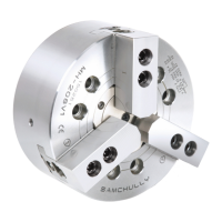
Top Jaw
Chuck
Chuck Adaptor
Draw pipe
Cylinder adaptor
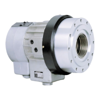
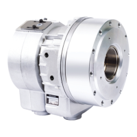
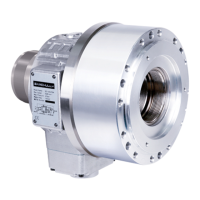
Cylinder
A
Support
NC Lathe
Wrench
Hex. socket
head bolt
Thread this screw in accordance
with that of a draw pipe.
Set Screw
Spring
Steel Ball
Plunger Nut
Chuck Body Wedge Plunger
Draw Nut
Type Cylinder a b c d(f7) e Min. f Max. L
MH-206
MHT-206
SD-
15452
M60
x
2.0P
30 25 55
-0.030
4
M60
x
2.0P
A+39
-0.060
MH-208
MHT-208
MHF-208
SD-
17568
M75
x
2.0P
35 30 70
-0.030
4
M75
x
2.0P
A+42
-0.060
MH-210
SD-
18582
M90
x
2.0P
40 28 85
-0.036
5
M90
x
2.0P
A+45
-0.071
MH-212
SD-
21510
M115
x
2.0P
45 30 110
-0.036
5
M116
x
2.0P
A+54
-0.071
MH-218
SD-
30516
M180
x
3.0P
55 60 170
-0.043
5
M175
x
3.0P
A+60
-0.083
MH-221
SD-
30516
M180
x
3.0P
55 45 170
-0.043
5
M180
x
3.0P
A+60
-0.083
MH-224
SHL-
39024
M250
x
3.0P
55 50 243
-0.050
5
M200
x
3.0P
A+65
-0.096
 Loading...