24
If the drawpipe is insufficiently screwed into the
drawnut, the thread will be damaged, thus elimi-
nating the gripping force momentarily. It will result
danger due to discharge of workpiece.
Tighten chuck mounting bolts at the specified
tightening. If the tightening torque is insufficient
or too strong, bolts will be damaged and the chuck
or workpiece may fall. Periodically check that bolts
are not loosened. Use only attached SAMCHULLY
brand bolts. In an unavoidable case, use bolt with
strength code 12.9(M22 more than:10.9)or more
and sucient length.
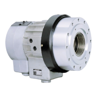
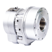
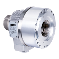
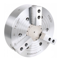
(2) Mount the cylinder to the spindle. (cylinder adap-
tor) Check that the run-out of cylinder is minimized
before routing the hydrauilc piping. Move the pis-
ton at low pressure (0.4Mpa~0.5Mpa 4~5kgf/cm)
two or three times and set the piston at the forward
end before switching power o.
(3) Connect the chuck to the drawpipe. Remove the
soft jaw and cover of the chuck to insert the con-
necting handle in to the central hole of the chuck.
Connect the chuck onto the drawpipe, turning the
drawnut.(Fig.4) If the connecting of the chuck and
drawpipe is dicult check the thread. If connected
by force, the plunger will be damaged, thus result-
ing in seizing.
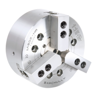
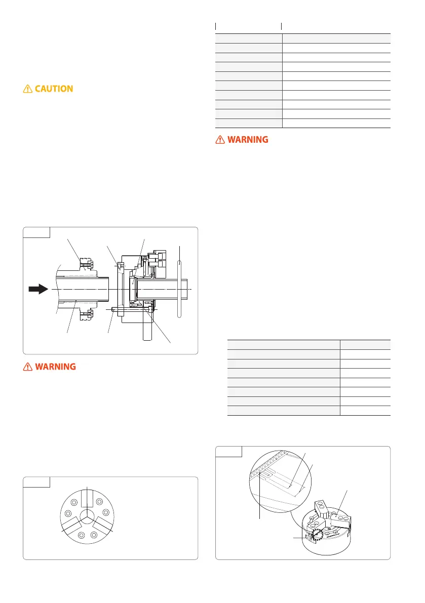
(5) Adjust the master jaw to the correct position. The
adequate master jaw position at the cylinder ad-
vance end is where dinension A from cover mount-
ing face is shown in the following table. (Fig.4) At
this time, Check the master jaw standard mark is
aligned to the outer line of total stroke mark.(Fig.6)
Since the clip stop (locking system) is provide to the
draw nut, adjust the nut where it is eectual.
(4) Mount the chuck to the spindle (back plate) Turn
the joint handles so that the chuck is prorerly at-
tached to the spindle mounting face of lathe. Uni-
formly tighten chuck mounting bolts in the order of
1,2,3,4,5 and 6 as shown in Fig.5
(Uneven tightening will cause run-out.)
When mounting or removing the chuck, lift it
with the crane, using an eyebolt or lifting belt.
(For a chuck of 8 inches or less, the eyebolt is not
attached) Be sure to remove the eyebolt from the
chuck after mounting or removing.
Bolt Tightening Steps
Bolt Size Tightening Torque
M5 7.8N·m(0.8kgf·m)
M6 12.7N·m(1.3kgf·m)
M8 38.2N·m(3.9kgf·m)
M10 72.6N·m(7.4kgf·m)
M12 106.8N·m(10.9kgf·m)
M14 170.6N·m(17.4kgf·m)
M16 250.0N·m(25.5kgf·m)
M20 402.1N·m(41.0kgf·m)
M22 539.4N·m(55.0kgf·m)
(6) Remount the cover and check run-out of the chuck.
Make peripheral run-out and face run-out of the
chuck to 0.02mm or less.
(7) Check the base line mark of master jaw is within the
range of the whole stroke.
Tightening Torque
g. 4
g. 5
g. 6
Advance end
Draw Pipe Mounting Bolt
Wedge Plunger
Spindle
Chuck Adaptor
Draw Nut
Joint Handle
Base Line Mark
Suitable Stroke
Whole Stroke
Master Jaw
Top Jaw
Type
A
MH-206 / MHT-206 21.0
MH-208 / MHT-208 / MHF-208 23.5
MH-210 21.5
MH-212 31.5
MH-218 28
MH-221 29
MH-224 29
 Loading...