62 | SAMLEX AMERICA INC.
SECTION 4 | Parameter Setup
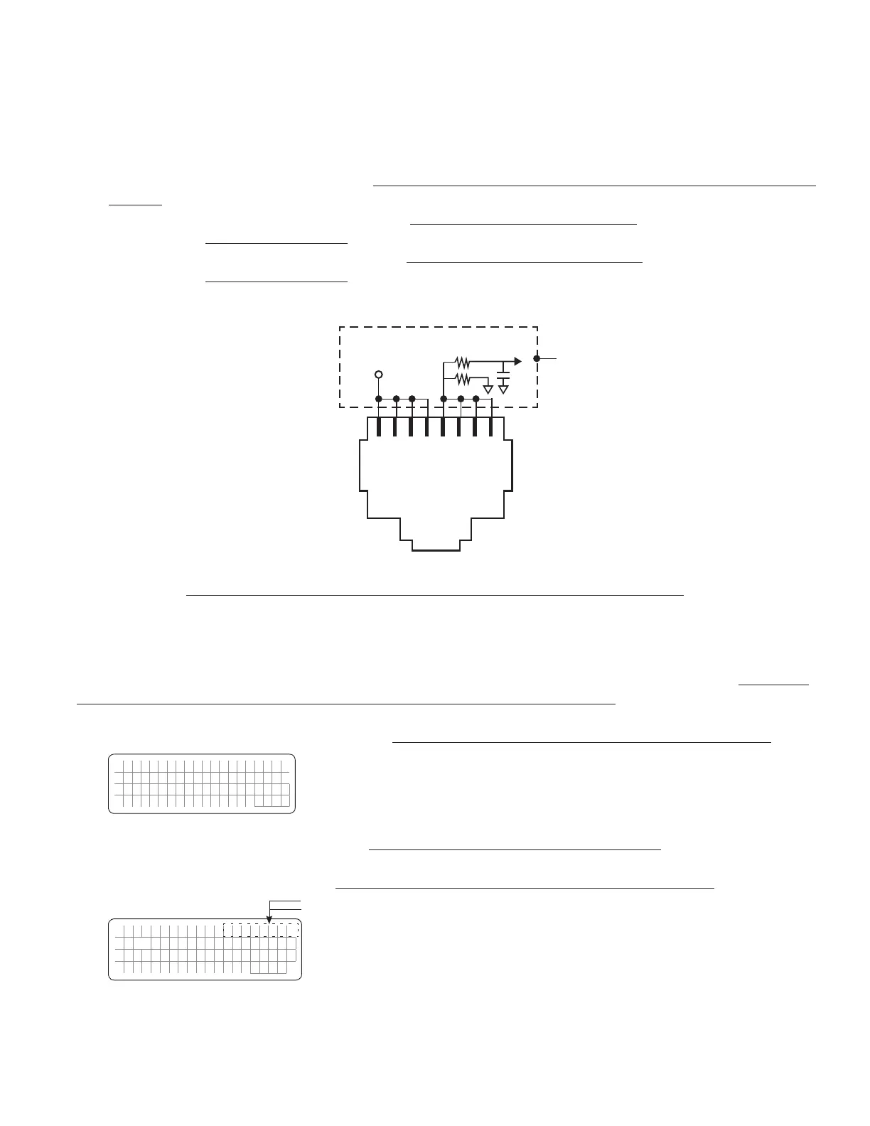
b) Wiring Connection: Output from the SSR Terminals on the Lithium Battery BMS should be wired to the RJ-
45 Jack marked “Battery Temp. Sensor” (6, Fig 2.1 in the EVO-1212F/1212F-HW/1224F/1224F-HW Owner's
Manual) as follows:
• Connect terminal marked “+” on the SSR (Drain of Mosfet switch inside SSR) to any of pins 1/2/3/4 of
RJ-45 Jack (Pinout shown below)
• Connect terminal marked “-” on the SSR (Source of Mosfet switch inside SSR) to any of pins 5/6/7/8 of
RJ-45 Jack (Pinout shown below)
1 2 3 4 5 6 7 8
+5V
Internal
Schematic
of EVO
TM
Batt Temp
to DSP
1K
5.1K
Pinout of RJ-45 Jack on the Front Panel of EVO Inverter/Charger
(6, Fig 2.1 in the EVO-1212F/1212F-HW/1224F/1224F-HW Owner's Manual)
When the Drain-Source terminals of the BMS close, Pins 1/2/3/4 and 5/6/7/8 of RJ-45 Jack will be shorted. The following
actions will be activated in EVO:
• EVO in Charging Mode: Charging will stop but AC input power will continue to be passed through (Internally,
the EVO will be in Charging Mode, but the charging current will be reduced to 0A). During this condition,
7 scrollable display screens will be available as shown in the Menu Map in Fig 3.7 that will include message
“Charger Off by BMS” in each of the 7 screens. Example of Screen No. 1 of the 7 Screens is shown below:
E V O - 1 2 1 2 F C h a r g i n g
C h a r g e r O f f b y B M S
B a t t : 1 2 . 0 0 V 0 . 0 A
E x t e r n a l :
0 . 0 A
• EVO in Inverting Mode: Inverting will stop (Internally, the EVO will enter Standby Mode). During this condition,
7 scrollable display screens will be available as shown in the Menu Map in Fig 3.8 that will include message “Inv
Stop by BMS” in each of the 7 screens. Example of Screen No. 1 of the 7 Screens is shown below:
E V O - 1 2 1 2 F I n v S t o p
A C o u t p u t : 0 . 0 0 V
< 0 . 1 0 A
0
. 0 0 H
z
"Inv stop" for 2 sec
"by BMS" for 2 sec
See NOTE 1
 Loading...