SAMLEX AMERICA INC. | 7
SECTION 2 | Installation
1. Cut an opening in the wall using the supplied Installation Template (based on Fig 2.1).
2. Drill four pilot holes (use 2mm / 5/64" diameter drill bit) for 4 screw (Self Taping, Flat Head No. 6 x 5/8" long) that
will attach the remote to the wall (refer to Fig. 2.1 for hole locations and dimensions).
3. Route one end of the cable through wall opening to the EVO™ Inverter/Charger, and then plug it into the RJ-45
Remote Control Jack port on the EVO™ Inverter/Charger
4. Take the other end of the remote cable and plug it into the RJ-45 / RJ-12 Jack at the back of the EVO-RC-PLUS
(Fig. 2.3).
5. Check the remote display to ensure the Power-up Self Test initiates.
6. If the self test is successful, secure the EVO-RC-PLUS to the wall using the four screws (Fig. 2.2).
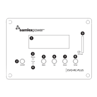
Flush mounting the EVO-RC-PLUS on the wall with 4 screws:
No. 6 x 5/8", Self Tapping, Flat Head.
Fig 2.2 EVO-RC-plus Flush Mounting
The thickness of the wall/panel board at the place of mounting should not be
more than 13 mm to ensure that the RJ-45 / RJ-12 jack openings are not obstructed.
Fig 2.3 Wall/Panel Thickness