SAMLEX AMERICA INC. | 91
SECTION 4 | Parameter Setup
4.8.2.5.2.3 Option 4 = Generator 2
This Option will start the Generator at “LOW VOLT ALARM” (Section 4.4.2.8) and stop the Generator after the desired
programmed value of run time of the Generator = “GEN ON TIME” (Section 4.4.2.17) counted from the time the Status
Relay is switched ON (energized). Further details are given below:
• If the battery voltage drops to “LOW VOLT ALARM” (Section 4.4.2.8) or lower for continuous period =
“GS DETECT TIME” (Section 4.4.2.16), the Status Relay will be switched ON (energized). “Common”
and “NO” contacts of the Status Relay will close to initiate automatic starting of the Generator.
• Once the generator has started and starts feeding AC output (within the programmed limits of voltage
and frequency), the EVO™ will change over from “Inverting Mode” to “Charging Mode”. Battery
charging will be initiated as per the Charging Prole set by parameter "CHARGING PROFILE" (Section
4.4.2.21).
• The Status Relay will be switched OFF (de-energized) after expiry of the desired programmed Generator
run time = “GEN ON TIME” (Section 4.4.2.17) counted from the time the Status Relay is switched
ON (energized). “Common” and “NO” contacts of the Status Relay will open to initiate automatic
stopping of the Generator. When AC output from the Generator switches OFF, EVO™ will change
over to “Inverting Mode” (NOTE: The State of Charge of the battery after the Status Relay has been
switched OFF (de-energized) and Generator is stopped will be indeterminate).
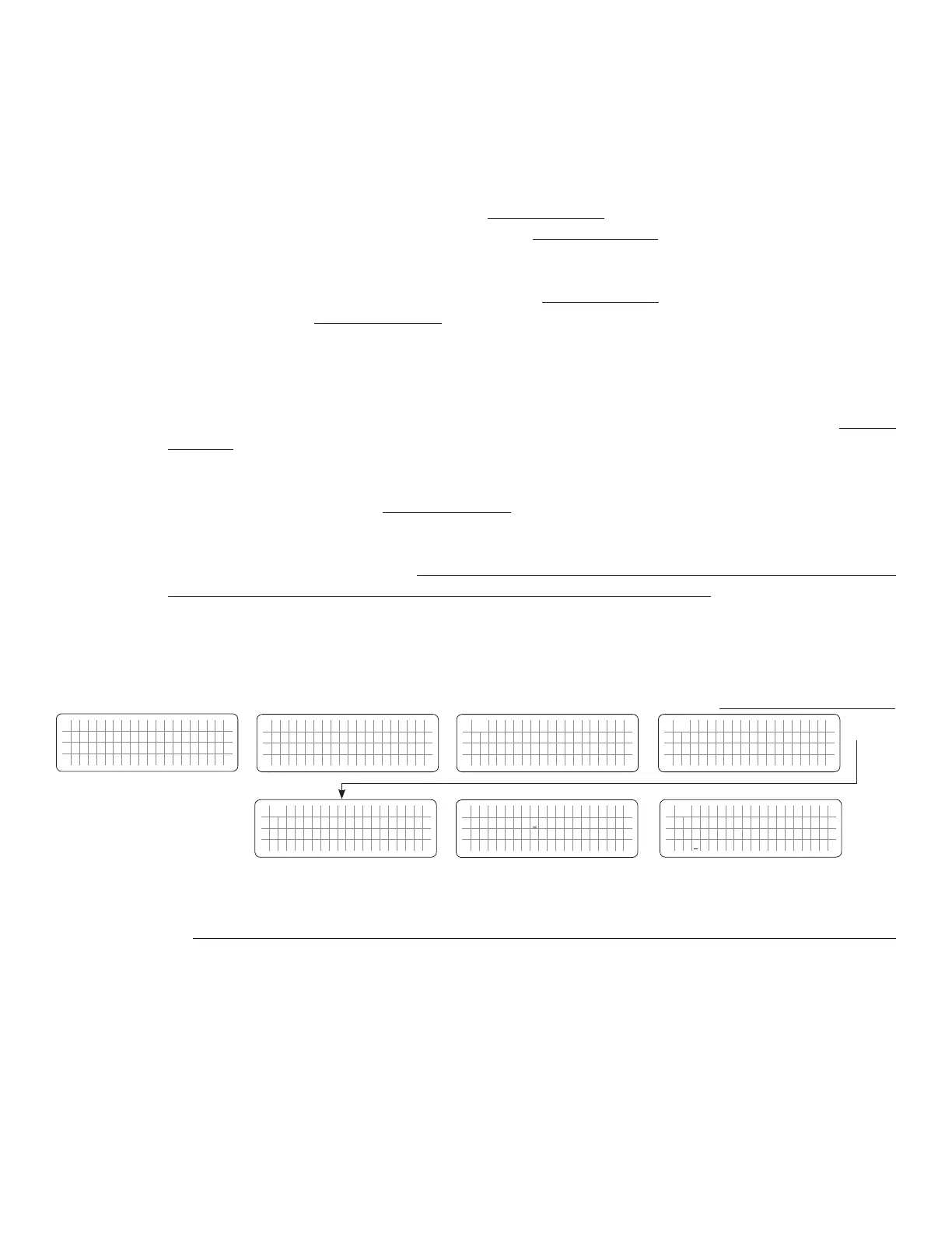
4.8.2.5.3 Programming Steps for Parameter "RELAY FUNCTION"
Diagram showing steps for programming the above RELAY FUNCTION is given below:
ð ð
E V O - 1 2 1 2 F I n v e r t i n g
A C o u t p u t : 1 2 0 . 0 V
< 0 . 1 0 A
6 0 . 0 0 H z
Enter Key
Down Key x 4 times
(Only for EVO-2212/3012/2224/4024)
Any Operating Mode Screen from
Fig 3.1 to 3.5
[Above screen is Screen 1 of Fig 3.2(a)]
Password 8052
See Section 4.3.1
See Table 4.9
for programmable options
S e l e c t G r o u p
* C H A R G E C U R V E
ð
S e l e c t P a r a m e t e r
* O T H E R F U N C T I O N
ð
S e l e c t P a r a m e t e r
O T H E R F U N C T I O N
* P O W E R S A V I N G
0 = D i s a b l e
S e l e c t P a r a m e t e r
O T H E R F U N C T I O N
* R E L A Y F U N C T I O N
2 = G e n e r a t o r 0
Down Key x 4 times
Enter Key
P a s s w o r d k e y i n
0 0 0 0
ð
Enter Key
S e l e c t P a r a m e t e r
O T H E R F U N C T I O N
* R E L A Y F U N C T I O N
2 = G e n e r a t o r 0
ð
Enter Key
4.8.2.6 COMM ID (Table 4.9, (i) Parameter Setup Screen No. 5 under Column 1 (ii) Parameter Setup Screen No. 6 under Column 2)
Communication ID- This sets the ID number for the COMM Port and EVO-RC/ EVO-RC-PLUS Remote Control.
 Loading...