EasyManua.ls Logo

Sampo Rosenlew Comia C6 - User Manual

Default Icon
141 pages
Print Icon
To Next Page IconTo Next Page
Loading...
Comia
0814374 04/2015
Englanti
Sampo Rosenlew Ltd
P. O. Box 50
FIN-28101 PORI FINLAND
Combine Harvester
Instruction Book
Question and Answer IconNeed help?

Do you have a question about the Sampo Rosenlew Comia C6 and is the answer not in the manual?

Summary

SAFETY PRECAUTIONS

DRIVING IN TRAFFIC

Procedures and warnings for driving the combine on public roads.

THRESHING

Safety measures and advice for the threshing operation.

SAFETY DISTANCES WHEN THRESHING UNDER OPEN-WIRE POWER LINES

Specifies safe distances from overhead power lines during operation.

In Case of an Accident

Steps to take in the event of an accident involving power lines.

FIRE SAFETY

Fire Safety Precautions

Guidelines and measures to prevent and handle fires.

MARKING THE DANGER POINTS

HAZARD PICTORIALS

ACCEPTANCE INSPECTION AND GETTING STARTED

Pre-start up checks

Essential steps before the initial operation of the combine.

STRUCTURE AND FUNCTIONS OF THE COMBINE

CUT - AWAY PICTURE OF THE COMBINE, Standard Threshing Mechanism

CUT - AWAY PICTURE OF THE COMBINE; the TS Threshing Mechanism

OPERATOR’S CONTROLS AND INSTRUMENTS

Operators Platform; Cab Controls

Identification of controls on the operator's platform.

Instrument Panel Controls

Identification of controls on the instrument panel.

Switches

Identification of various switches for combine functions.

SIGNALS AND SYMBOLS

Control Signals and Symbols

Explanation of dashboard signals, warning lights, and symbols.

OPERATION AND ADJUSTMENT

BRAKES (Fig. K3 a) While Driving and Turning

Driving Brakes

How driving brakes operate and are used.

Starting the ENGINE with Ignition Key

TRANSMISSION, hydrostatic

Hydrostatic Transmission Speed Ranges

Selecting and using the hydrostatic transmission speed ranges.

Optional Differential Lock

Differential Lock Usage and Engagement

Usage and engagement of the differential lock.

TOWING (Figs. K16 and K17) Allowed from Towing Points Only

SAFETY SWITCH

Safety Switch Functionality

How the safety switch prevents unintended operation of mechanisms.

WARNING LIGHTS and CONTROL LIGHTS (fig. L2) warn

Control Light Indicators

Meaning of control lights on the right A-pillar.

The engine display

Engine Display Modes 1-4

Explanation of different display modes for engine information.

Engine Display Modes 5-8

Explanation of additional display modes for engine information.

Self-diagnostics and Fault Reporting

How the self-diagnostics monitor engine functions and report faults.

THRESHING EQUIPMENT

The REEL Has Four Adjustable Settings

CUTTING KNIFE Must Be Kept in Good Condition!

CUTTING AND FEEDING MECHANISM REVERSE DRIVE

Height of the CUTTING TABLE (Figs. L12 c, L13 c and L14 c)

Stepless Control of THRESHING CYLINDER Speed (fig. L18 b)

Threshing Cylinder Speed Control

How to adjust the threshing cylinder speed.

Adjusting of the CONCAVE Clearance (figs. L20 a and L22 a)

Concave Clearance Adjustment

Adjusting the clearance between the concave and threshing cylinder.

Adjusting of PRE-CONCAVE

Pre-concave Clearance Adjustment

Adjusting clearance between pre-concave and pre-cylinder.

SHAKER SHOE Adjustments (Fig. L28)

CLEANING FAN (Figs. L32, L33 and L34) Provides Sufficient Air Flow

Safe Working in the GRAIN TANK (Figs L38 b and L39 b)

Grain Tank Cover Operation

How to operate and secure the grain tank cover.

Turning and Operating of the UNLOADING PIPE (Figs. L41 c)

Danger Zone behind the STRAW CHOPPER (Figs. L45, L46 and L47)

Straw Chopper Danger Zone and Adjustments

Awareness of the danger zone and adjustments for chopper degree.

ENGINE, Source of Power

SCR Technology and DEF Handling

Lubrication System

COMVISION

COMVISION Monitor Overview

Introduction to the COMVISION monitor and its functions.

Work monitor

Work Monitor Display

What is displayed on the normal work screen of the monitor.

Meter Display Options

How to access and select different meters on the monitor.

Display Mode Details (L60, L61)

Details of various display modes for engine and other parameters.

Shaft Revolutions and Alarms

Viewing and adjusting shaft speeds and alarms on the monitor.

Settings

Machine Settings Menu

Accessing machine settings for alarms and calibrations.

Alarms Window (Page #1)

Overview of alarms for chopper, thresher, fan, and elevators.

Alarms Window (Page #2)

Overview of alarms for straw walker, feeder, reel, and grain tank.

Alarm Window Example and Information

Example of an alarm window and how to get more information.

Calibration Procedures

How to perform calibrations for grain loss and working width.

Speed and Header Height Calibration

Calibrating speed and header height settings.

Test Menu Functions

Using the test menu to check inputs and outputs.

Data

Data Menu Options

Viewing job, total, campaign, engine data, and alarm logs.

Gauge

Console menu

Operation; adjustment

Service

DHC

Presetting of Cutting Height

Using the DHC system to preset cutting height.

DRIVING AND THRESHING INSTRUCTIONS

Before Starting the Combine Check

Pre-start checks for the combine.

Starting the Engine

Procedure for starting the engine with hydrostatic transmission.

When Driving on the Road

Road Driving Precautions

Procedures and precautions for driving on roads.

When Driving on the Field

Field Driving Precautions

Procedures and precautions for driving in the field.

In Soft Field Conditions

On Steep Slopes

Threshing Instructions

Choose the Correct Time and Conditions

Advice on selecting optimal conditions for harvesting.

Good Threshing Results with Even Feed

Tips for achieving good threshing results with consistent feed.

Reel Position in Accordance With Crop

Reel Position Adjustment

Adjusting reel position based on crop type and condition.

Adjust the straw dividers to reduce table losses and improve feeding

Estimation of Threshing Losses

Causes for table loss:

Malfunction Problems

Troubleshooting Common Malfunctions

Troubleshooting common malfunction problems like cylinder or auger clogging.

Cleaning Instructions When Going From One Crop To Another

APPROXIMATE SETTINGS

Threshing Cylinder and Concave Settings

Recommended settings for threshing cylinder and concave.

Shaker Shoe and Fan Settings

Recommended settings for shaker shoe and fan.

SERVICE AND MAINTENANCE

The Functioning of the Combine Is Based on the Condition of the KNIFE

CHANGING OF THE KNIFE

Replacing of a KNIFE SECTION

Alignment of the KNIFE FINGERS

TABLE AUGER FINGERS Must Be Straight

Check the OVERLOAD CLUTCHES of the CUTTING TABLE

Removing of the TABLE in the Correct Order

Cylinder;Concave CLEARANCE

Cylinder;Concave Clearance Check and Adjustment

Checking and adjusting cylinder-concave clearance.

Checking of PRE-CYLINDER Clearance, Fig. P23

Pre-Cylinder Clearance Check and Adjustment

Checking and adjusting pre-cylinder clearance.

BELT TENSIONING

FAN VARIATOR BELTS

THRESHING CYLINDER VARIATOR BELT

RETURN AUGER BELT and Overload Clutch

DRIVE BELT IN THE HYDRAULIC TRANSMISSION

CUTTING TABLE CLUTCH BELT

CUTTING TABLE DRIVE BELT

REEL VARIATOR BELTS

KNIFE DRIVE BELT

BELTS WITH FIXED TENSION

Changing of CHOPPER KNIVES

Chopper Knife Replacement

Procedures for replacing worn or damaged chopper knives.

Removing and Refitting of a Bearing Locked with an ECCENTRIC RING

Adjustment of DRIVING BRAKES

Driving Brake Adjustment

Adjusting the driving brakes for wear and free travel.

ENGINE

Oil Change and Filter Replacement

Procedures for changing engine oil and oil filter.

Fuel Filters Maintenance

Maintenance of fuel pre-filter and primary filter.

Air Filter

COOLING SYSTEM

GEARBOX (Fig. R1)

CLOSED FINAL DRIVES (Figs. R2 a and R2 b) on Models Equipped with Them

KNIFE DRIVE UNIT (Fig. R3)

GEAR BOX IN THE RETURN AUGER (Fig. R4)

DIFFERENTIAL LOCK (Fig. R5)

Differential Lock Adjustment

Adjusting the differential lock for proper function.

HYDRAULICS

General Description of Hydraulics

Overview of the hydraulic systems and their components.

ELECTRICAL SYSTEM

Alternator and Master Switch

Function of the alternator and master switch.

Fuse Locations and Functions

Location and purpose of fuses in the electrical system.

Fuses

Main Fuses and Fuse Box Identification

Details of main fuses and fuse box locations.

Fuses (Circuit Board)

List and amperage of fuses on the circuit board.

Fuses (Rear Switchboard)

List and amperage of fuses in the rear switchboard.

Switchboard Relays

Identification and function of relays in the switchboard.

CTA engines (COMMON RAIL)

3 B Engine Relays

Sensors of ELECTRICAL SPEEDOMETERS

Electrical Speedometer Sensor Function

How electrical speedometer sensors function and their adjustment.

BATTERY

LUBRICATION

Lubrication Table and Recommendations

Table of recommended lubricants, grades, quantities, and intervals.

LUBRICATION DIAGRAM

SUMMARY OF PERIODICAL MAINTENANCE PROCEDURES

Daily Maintenance Checks

List of daily maintenance tasks.

Every 50 Working Hours Maintenance

Maintenance tasks for every 50 working hours.

Every 300 Working Hours or Yearly Maintenance

Maintenance tasks for 300 hours or yearly.

Every 600 Working Hours or Yearly Maintenance

Maintenance tasks for 600 hours or yearly.

Every 1200 Working Hours or Every Other Year Maintenance

Maintenance tasks for 1200 hours or every other year.

STORAGE WHEN NOT IN USE

Cleaning for Storage

Procedures for cleaning the combine before storage.

Checking for Storage

What to check and record before storing the combine.

Protection Measures for Storage

Protective measures for parts during storage.

Pre-storage Service of Engine

Engine Preparation for Storage

Engine preparation for storage.

Other Pre-storage Measures

After-storage Attention

Post-storage Checks and Procedures

Checks and procedures after removing the combine from storage.

CONVERSION FOR MAIZE HARVESTING

Required Components for Maize Conversion

List of components needed for maize harvesting conversion.

Maize Header Installation Steps

Steps for removing the cutting table and installing the maize header.

Drive Chain and Pulley Installation

Maize Conversion Drive Chain Installation

Installing drive chains and pulleys for maize harvesting.

Modifications in the Cylinder Area

Straw Chopper Modification

Special Instructions for Maize Harvesting

Specific adjustments for maize harvesting (Feeder Elevator, Concave).

Modification back to Cereal Harvesting

Cereal Harvesting Conversion Procedure

Procedures for converting back from maize to cereal harvesting.

THRESHING EQUIPMENT TO BE USED WITH SUNFLOWER

Cutting Table Modifications for Sunflower

Adapting the cutting table for sunflower harvesting.

Sunflower Equipment Fitting

Fitting tray clamps and screen plates for sunflower.

Fitting of the Side Guides

Sunflower Side Guide Fitting

Fitting side guides for sunflower harvesting.

Fitting of the Trays

Sunflower Tray Fitting

Fitting center and outer trays for sunflower.

Fitting of the Pick-up Reel Plates

Pick-up Reel Plate Fitting

Fitting guard plates to pick-up reel tines.
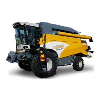
Sampo Rosenlew Comia C6 Specifications

General IconGeneral
TypeCombine Harvester
Number of Straw Walkers5
TransmissionHydrostatic
Number of Gears4
Fuel Tank Capacity300 liters
Hydraulic SystemClosed center
Height3, 900 mm
CabinYes

Related product manuals