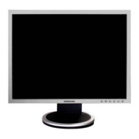
Do you have a question about the Samsung 203B - SyncMaster - 20" LCD Monitor and is the answer not in the manual?
Describes the front panel buttons and their functions for OSD and MagicBright.
Details the rear panel ports and power switch for connecting cables and power.
Instructions on how to use and adjust the monitor stand, including removal and attachment.
Step-by-step guide for disassembling the monitor, with cautions for ESD.
Reassembly procedures are the reverse of the disassembly steps. Ensure correct reassembly.
Identifies major components like Scaler, DDR Memory, and MICOM on the PCB.
Explains the function and interaction of the main blocks like Scaler, DDR Memory, and MICOM.
Defines various technical terms used in the manual, like TFT-LCD, ADC, and DVI.
Lists pin assignments for D-Sub and DVI connectors, detailing signal types and functions.
Provides a chart detailing timing parameters for various IBM and VESA display modes.
Lists preset timing modes for computer signals to ensure proper display adjustment.
Lists various panel models, vendor P/Ns, and associated remarks or specifications.
Highlights key design and application features of the monitor, like HAS and rotation.
Provides detailed technical specifications including LCD panel, resolution, frequency, and dimensions.
Details specific features and operating methods for the LS20BRD model.
Compares key specifications between the LHA20BS and LS20BRD models.
Lists optional accessories and their corresponding part numbers and remarks.
Provides a flowchart to diagnose and resolve issues related to the monitor not powering on.
Offers troubleshooting steps for cases where no video signal appears from an analog PC connection.
Provides troubleshooting guidance for no video output when using a digital PC signal.
Visual diagram showing the exploded components of the round simple stand model.
Visual diagram showing the exploded components of the sliding HAS stand model.
Comprehensive list of electrical components and their part numbers for the round simple stand.
First part of the schematic diagrams, showing circuit layouts and connections.
Second part of the schematic diagrams, illustrating further circuit details and connections.

