81
4. Electrical Wiring Diagram
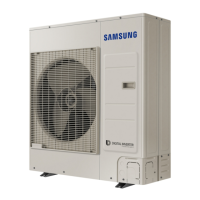
Outdoor Units
AC100/120/140MXADNH
MAIN PCB Printed circuit board(MAIN) EEV Electronic Expansion Valve DIS-TEMP Thermistor DISCHARGE
INVERTER PCB Printed circuit board(INVERTER) M-BLDC
BLDC Motor
OUT-TEMP Thermistor AMBIENT
EMI PCB Printed circuit board(EMI)
OLP-TEMP Thermistor OLP COND-TEMP Thermistor CONDENSOR
NOTE
• This wiring diagram applies only to the outdoor unit.
• Colors blk: black, red: red, blu: blue, wht: white, yel: yellow, brn: brown, sky: skyblue
• When operating, don’t shortcircuit the protection device (High Pressure switch)
• For connection wiring indoor-outdoor transmission F1-F2, outdoor-outdoor transmission OF1-OF2, refer to
the installation manual.
•
Protective earth(screw), : connector, : The wire quantity
 Loading...