Samsung Electronics 8-2
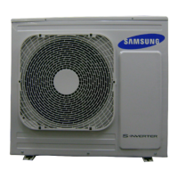
■ Condenser
Gas refrigerant discharged from the compressor is cooled down in the condenser of the outdoor unit by means of thermal emission
and turned into a liquid refrigerant before being sent to the evaporator.
■ Compressor
It compresses the low-temperature, low-pressure refrigerant to let it flow to the Cycle.
■ Evaporator
As the liquid refrigerant that has been absorbed via capillary tubes evaporates (from liquid to gas), it absorbs heat from the surround-
ings, thereby cooling the indoor area.
■ Service Valve
Using a hex wrench, turn the needle valve counterclockwise to open the valve. It is used for vacuuming, gas drain, refrigerant
injection, refrigerant purge, and indoor-outdoor units connection.
■ Accumulator
It prevents liquid refrigerant from flowing into the compressor.
(If liquid refrigerant enters the compressor, it becomes overloaded)
8-2 Refrigerating Cycle Diagram
Cooling
Heating
Gas Leak Check Point
Indoor Unit
Outdoor Unit
T1
T2
Heat
Exchanger
(Evaporator)
Heat
Exchanger
(Condenser)
Propeller Fan
Cross Fan
2 way valve
Capillary tube
Capillary tube
Check valve
※Note
3 way valve
4 way valve
Gas side
Liquid side
Compressor
 Loading...
