
A
Alan MunozAug 18, 2025
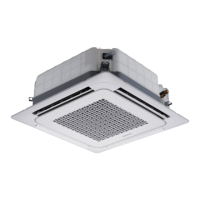
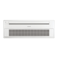
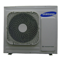
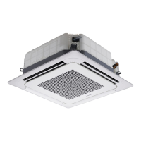
What to do if my Samsung Air Conditioner displays error E201?
- HhernandezrobinAug 18, 2025
If your Samsung Air Conditioner displays error code E201, it indicates a communication tracking failure after the initial power supply. This error occurs regardless of the number of units. To resolve this, check the indoor quantity setting in the outdoor unit.