EasyManua.ls Logo

Samsung AM012HNQDCH/AA User Manual

Samsung AM012HNQDCH/AA
404 pages
To Next Page IconTo Next Page
Page #1 background imageLoading...
Page #1 background image
SYSTEM AIRCONDITIONER CONTENTS
SYSTEM AIRCONDITIONER
INDOOR UNIT
AM007/009/012FN1DCH/AA
AM009/012/018/020FNNDCH/AA
AM009/012/018/024/030/036/048FN4DCH/AA
AM007/009/012FNLDCH/AA
AM018/024FNLDCH/AA
AM030/036/048FNLDCH/AA
AM018/024FNMDCH/AA
AM030/036FNMDCH/AA
AM048FNMDCH/AA
AM007/009/012/018/020/024FNTDCH/AA
AM007/009/012/018/020/024HNQDCH/AA
AM036/048FNHDCH/AA
AM076/096FNHDCH/AA
AM018/024FNCDCH/AA
AM048/096HNPDCH/AZ
AM007/009/012/015/018JNMDCH/AA
AM024/027/030/036/048JNHDCH/AA
AM036/048JNCDCH/AA
AM006/009/012/018/024JNFDCH/AA
AM006/009/012/018/024JNGDCH/AA
AM072/096JNESCH/AA
AM054KNMDCH/AZ
AM007/009/012/018/020/024KNQDCH/AZ
AM007/009/012/018/020/024KNTDCH/AZ
AM005/007/009/012/015/018/024/028MNVDCH/AA
AM007/009/012NN1DCH/AA
AM009/012/018/024/030/036/048KN4DCH/AA
AM007MNMDCH/AA
AM009MNMDCH/AA
AM012MNMDCH/AA
AM015MNMDCH/AA
AM018MNMDCH/AA
AM024MNMDCH/AA
AM027MNMDCH/AA
AM030MNMDCH/AA
AM036MNMDCH/AA
AM048MNMDCH/AA
AM032MNQDCH/AA
AM007NN1DCH/AZ
AM009NN1DCH/AZ
AM012NN1DCH/AZ
AM018NN1DCH/AZ
AM024NN1DCH/AZ
1. Precautions
2. Product Specifications
3. Disassembly and Reassembly
4. Troubleshooting
5. PCB Diagram and Parts List
6. Wiring Diagram
7. Reference Sheet

Table of Contents

Questions and Answers:

Samsung AM012HNQDCH/AA Specifications

General IconGeneral
ModelAM012HNQDCH/AA
Cooling Capacity12000 BTU/h
Cooling Capacity (Tons)1 Ton
RefrigerantR410A
Noise Level (Outdoor)50 dB(A)
Heating Capacity12000 BTU/h
TypeSplit
Coefficient of Performance (COP)3.5 COP
Indoor Unit Dimensions (W x H x D)31.5 x 11.4 x 8.7 inches
Outdoor Unit Dimensions (W x H x D)21.3 inches

Summary

Precautions

1-1 Precautions for the Service

Guidelines for safe and correct service procedures.

1-2 Precautions for the Static Electricity and PL

Handling precautions for static electricity and PL.

1-3 Precautions for the Safety

General safety measures to prevent electric shock and fire.

1-4 Precautions for Handling Refrigerant for Air Conditioner

Guidelines for safe handling of refrigerant to prevent pollution.

1-5 Precautions for Welding the Air Conditioner Pipe

Safety measures for welding air conditioner pipes.

1-6 Precautions for Additional Supplement of Air Conditioner Refrigerant

Procedures for safely supplementing refrigerant.

Product Specifications

2-1 Product Specifacations

Detailed specifications for various indoor unit models.

2-1-1 Indoor Unit

Specifics on Indoor Unit specifications including Slim 1WAY cassette.

2-2 Accessory and Option Specifications

Specifications for optional accessories and features.

Disassembly and Reassembly

3-1 Indoor Unit

Procedures for disassembling and reassembling indoor units.

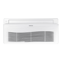
Slim 1 way cassette type

Step-by-step guide for disassembling Slim 1 way cassette indoor units.

Wind-free 1way cassette type

Disassembly procedures for Wind-free 1way cassette indoor units.

BIG DUCT

Disassembly procedures for BIG DUCT type indoor units.

Duct type(Slim3)

Disassembly procedures for Slim3 duct type indoor units.

Wall mounted type (Neo forte)

Disassembly procedures for Neo Forte wall-mounted indoor units.

Wall Mounted type (A3050)

Disassembly procedures for A3050 Wall Mounted indoor units.

360 Cassette Type

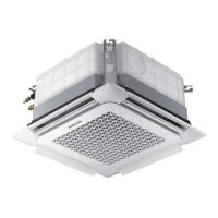
Disassembly procedures for 360 Cassette type indoor units.

Troubleshooting

4-1 Check-up Window Description

Explanation of the check-up window on the main PCB and its functions.

4-2 Service Operation

Special service operations and their key inputs for the outdoor unit.

4-3 Troubleshooting

General troubleshooting steps and option setting methods.

4-4 Appropriate Measures for Different Symptom

Diagnostic flowcharts and solutions for various symptoms.

4-4-3 Indoor Unit ROOM sensor Error (Open/Short)

Troubleshooting steps for indoor room sensor errors.

4-4-4 Indoor unit EVAP IN sensor Error (Open/Short)

Troubleshooting steps for indoor EVAP IN sensor errors.

4-4-19 Error due to incorrect Indoor Unit Power/Communication Cable Connection

Troubleshooting steps for incorrect indoor unit power or communication cable connection.

4-4-29 MCU branch part setup error – inconsecutive connection with the use of 2 branch parts

Troubleshooting MCU branch part setup errors related to consecutive connections.

PCB Diagram and Parts List

5-1 Indoor Unit

PCB diagrams and parts lists for various indoor units.

5-1-1 Slim 1 way cassette type

PCB diagram and parts list for Slim 1 way cassette indoor unit.

5-1-2 4way cassette , mini 4way casette type

PCB diagrams and parts lists for 4way and mini 4way cassette types.

5-1-3 Duct type (SLIM Duct 1,2)

PCB diagrams and parts lists for SLIM Duct 1,2 type.

Wiring Diagram

6-1 Indoor

Wiring diagrams for indoor units.

6-1-1 Global 4way(Global Mini-4way) cassteet type

Wiring diagram for Global 4way and Mini 4way cassette types.

6-1-2 Slim 1way cassette type

Wiring diagram for Slim 1way cassette type.

6-1-4 Ceiling

Wiring diagram for Ceiling type indoor units.

Reference Sheet

7-1 Index for Model Name

Index to understand model naming conventions for indoor units.

7-1-1 Indoor Unit

Detailed breakdown of indoor unit model code structure.

7-2 Pump-down Method

Procedures and precautions for refrigerant pump-down.

7-2-1 Precautions for Pump-down

Safety guidelines and considerations before performing pump-down.

7-2-2 For Single Installation of Outdoor Unit (Only One Outdoor Unit Installed)

Pump-down procedure for single outdoor unit installations.

7-2-3 When Two or More Outdoor Units are Installed

Pump-down procedure for multiple outdoor unit installations.

7-3 How to Put Refrigerant in Refrigerant Container

Method for safely putting refrigerant into a container before pump-down.

7-3-1 How to put refrigerant in container before pump-down

Step-by-step guide for refrigerant container preparation before pump-down.

Related product manuals