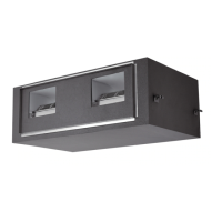
Do you have a question about the Samsung AM220KXVAGH/ET and is the answer not in the manual?
Detailed specifications for the outdoor unit, covering type, model, power, capacity, and fan.
Specifications for AM240KXVAGH/ET through AM300KXVAGH/ET, covering dimensions and operating ranges.
Disassembly and reassembly steps for electrical parts of specific outdoor unit models.
Disassembly steps for refrigerant cooling parts and internal components of specific outdoor unit models.
Disassembly and reassembly steps for electrical parts of AM140FXVAGH and AM140JXVGH models.
Disassembly steps for refrigerant cooling parts and internal components of specific outdoor unit models.
Disassembly steps for electrical parts of specific outdoor unit models, including cabinet and control box.
Disassembly steps for refrigerant cooling parts and internal components of specific outdoor unit models.
Disassembly steps for electrical parts of specific outdoor unit models, including cabinet and control box.
Disassembly steps for refrigerant cooling parts and internal components of specific outdoor unit models.
Disassembly steps for electrical parts of specific outdoor unit models, including cabinet and control box.
Disassembly steps for refrigerant cooling parts and internal components of specific outdoor unit models.
Procedure for discharging high DC voltage from the inverter PCB before handling it.
Table mapping DVM S models to Inverter PBA and EEP codes for troubleshooting.
Continuation of the EEPROM code table for DVM S models, including ASSY PCB INVERTER.
Explanation of error codes related to indoor unit communications, settings, and hardware.
Explanation of error codes related to compressor, Fan, and inverter PBA for outdoor units.
Flowchart detailing the steps for performing an outdoor unit test operation.
Procedure to check for reversed or missing phase on 3-phase power systems, indicated by E425 error.
Procedure for initial tracking and communication check, displaying E201 if issues arise.
Troubleshooting steps for the Main PCB when it has no power, indicated by a blank 7-segment display.
Troubleshooting steps for communication errors between indoor and outdoor units during tracking.
Troubleshooting steps for communication errors that occur after tracking, focusing on PCB address and cable checks.
Troubleshooting for communication errors between main/sub outdoor units or between multiple outdoor units.
Troubleshooting steps for internal communication errors within the outdoor unit's C-Box.
Troubleshooting steps for internal PCB communication errors within the outdoor unit's C-Box (E206 C001, C002).
Troubleshooting steps for internal PCB communication errors within the outdoor unit's C-Box (E206 C003, C004).
Troubleshooting for MCU branch setup errors when using 2 branch parts without consecutive connection.
Troubleshooting for MCU branch setup errors due to repeated address setup for the same address more than 3 times.
Troubleshooting for MCU branch setup errors when an indoor unit is not installed but registered.
Troubleshooting for MCU branch setup errors related to incorrect MCU quantity or duplicated addresses.
Troubleshooting for MCU branch setup errors due to overlapping indoor unit address setup.
Troubleshooting for MCU branch setup errors when the branch part is used but not connected to an indoor unit.
Troubleshooting for MCU branch setup errors when an indoor unit is connected to an unused branch part.
Troubleshooting for MCU branch setup errors when the number of connected indoor units exceeds the MCU setup.
Troubleshooting for MCU/Subcooler sensor errors (Open/Short), involving resistance checks.
Troubleshooting for outdoor temperature sensor errors (Open/Short), involving connector and resistance checks.
Troubleshooting for Cond Out temperature sensor errors (Open/Short), involving connector and resistance checks.
Troubleshooting for outdoor Cond Out sensor breakaway errors, including attachment and resistance checks.
Continuation of troubleshooting for outdoor Cond Out sensor breakaway errors, including resistance and path checks.
Troubleshooting for compressor discharge or top temperature sensor errors, involving connector and resistance checks.
Troubleshooting for compressor discharge/top sensor breakaway errors, including attachment and resistance checks.
Troubleshooting for suction temperature sensor errors (Open/Short), involving attachment and resistance checks.
Troubleshooting for high pressure sensor errors (Open/Short), involving connector, voltage, and pressure checks.
Troubleshooting for low pressure sensor errors (Open/Short), involving connector, voltage, and refrigerant checks.
Troubleshooting for suction-2 temperature sensor errors, involving connector and resistance checks.
Troubleshooting for liquid pipe temperature sensor errors, involving connector and resistance checks.
Troubleshooting for EVI In temperature sensor errors, involving connector and resistance checks.
Troubleshooting for EVI Out temperature sensor errors, involving connector and resistance checks.
Troubleshooting for suction-2 temperature sensor errors, involving connector and resistance checks.
Troubleshooting measures for various outdoor unit errors, including fan and compressor connection issues.
Troubleshooting for compressor down errors caused by high pressure protection, involving sensor and valve checks.
Continuation of troubleshooting for compressor down errors due to high pressure protection, involving water pipes and EEV checks.
Troubleshooting for compressor down errors caused by low pressure protection, involving sensor and valve checks.
Continuation of troubleshooting for compressor down errors due to low pressure protection, involving water pipes and refrigerant checks.
Troubleshooting for startup suspension due to discharge/top temperature sensor errors, involving resistance checks.
Troubleshooting steps for 3-phase input wiring errors, checking power connections, reactor, and EMI PCB.
Troubleshooting for startup suspension due to abnormal compression ratio, involving sensor and valve checks.
Troubleshooting for EVI EEV open errors, involving connector, coil, intercooler, and indoor EEV checks.
| Brand | Samsung |
|---|---|
| Model | AM220KXVAGH/ET |
| Category | Air Conditioner |
| Language | English |


 Loading...