Do you have a question about the Samsung AMxxxJXV Series and is the answer not in the manual?
| Refrigerant | R410A |
|---|---|
| Power Supply | 220-240V, 50Hz |
| Operating Temperature (Cooling) | 18°C to 43°C |
| Operating Temperature (Heating) | -7°C ~ 24°C |
| Weight (Outdoor Unit) | 35 kg |
Details hazards and unsafe practices leading to severe personal injury or death.
Highlights critical installation warnings and potential hazards for safe operation.
Guidelines for safely storing or disposing of packaging materials to prevent injury.
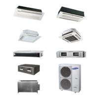
Details on compatible indoor and outdoor units and their capacity limits.
Diagrams and dimensions for single outdoor unit installation space.
Diagrams and dimensions for multiple outdoor unit installation space.
List of optional accessories for connecting pipes between indoor and outdoor units.
Details on base ground construction, including dimensions, leveling, and draining.
Specifications for outdoor unit base mount and anchor bolt placement.
Illustrations and guidelines for proper draining work for outdoor units.
Precautions for connecting anchor bolts, including material and tightening torque.
Cautions for connecting pipes, including rooftop installation and animal entry prevention.
Precautions for installing anti-vibration frames, ensuring proper contact and support.
Warnings regarding fan guard removal, safety nets, and protection equipment for discharge ducts.
Guidance on installing outdoor units near obstacles like balconies or in mechanical rooms.
Measures for preventing snow accumulation and selecting appropriate louvers.
Cautions for frame and base ground installation height and area concerning snowfall.
Requirements for protection walls or wind ducts in windy regions for optimal performance.
Guidelines for refrigerant pipe length, height difference, and cleanliness.
Determining pipe size based on outdoor unit capacity and length.
Table for selecting main pipe size based on outdoor unit capacity and maximum pipe length.
Selecting pipe size between branch joints based on indoor unit capacity and branch pipe length.
Selecting pipe size based on indoor unit capacity.
Model names and specifications for Y-joints and distribution headers between outdoor units.
Selecting first branch joints based on outdoor unit capacity.
Selecting Y-joints and distribution headers for connecting indoor units.
Crucial step for ensuring correct refrigerant charge based on system configuration.
Methods for calculating refrigerant amounts based on pipe length, size, and unit capacity.
Basic refrigerant charge amounts for various outdoor unit models.
Calculating additional refrigerant based on liquid pipe size and length.
Determining additional refrigerant for each indoor unit based on capacity and connection type.
Step-by-step example of calculating refrigerant for HR models.
Specifications for refrigerant pipe temper grade and minimum thickness.
Methods for preventing foreign materials or water from entering pipes during storage.
Critical safety information and procedures for welding refrigerant pipes.
Procedure for nitrogen flushing during welding to prevent oxidation and contamination.
Guidance on the correct pipe orientation for welding to avoid damage.
Essential steps for properly cutting and flaring refrigerant pipes.
Description of tools used for pipe flaring and their usage.
Illustrations showing correct and incorrect examples of flared pipe connections.
Procedure for connecting flared pipes using torque wrenches and proper tightening.
Guidance on routing refrigerant pipes for outdoor units, considering connections and direction.
Precautions for using knock-out holes, including preventing damage, rust, and animal entry.
Detailed procedures for connecting refrigerant pipes to various outdoor unit sides.
Procedure for connecting refrigerant pipes to the front side of the outdoor unit.
Procedure for connecting refrigerant pipes to the right/left/bottom sides of the outdoor unit.
Cautions during pipe welding to outdoor units, protecting sensors and preventing damage.
Guidelines for connecting pipes between multiple outdoor units in module configurations.
Illustrations showing correct and incorrect pipe installations for outdoor units.
Details on direct-connected indoor units without MCU for HR systems.
Guidelines for maximum allowable pipe length in single and module installations.
Limits on height difference between indoor and outdoor units and between connected units.
Limits for pipe length after branch joints for different connection types.
Information on EEV kit usage for specific indoor units and actual pipe length.
Instructions for setting MCU addresses and configuring ports using DIP switches.
Procedure for manually setting pipe addresses using remote control or S-NET Pro 2.
Instructions for setting pipe addresses using S-NET Pro 2 software.
Automated process for setting pipe addresses and verifying connections.
Checklist of items before starting auto pipe pairing operation for correct setup.
Step-by-step guide to initiating and performing the auto pipe pairing operation.
Interpreting results and error codes from the auto pipe pairing operation.
Guidelines for horizontal installation of branch joints.
Guidelines for vertical installation of branch joints.
Procedure for insulating distribution headers and fixing them with hangers.
Instructions for horizontal installation of distribution headers, ensuring ports do not face down.
Guidelines for connecting pipes between multiple outdoor units in module configurations.
Diagrams for installing outdoor joints, including correct and incorrect orientations.
Technical specifications for different MCU models, including port capacity and maximum connected capacity.
Illustrations showing how to connect indoor units to MCU ports.
Illustrations showing indoor unit connection in series via MCU.
Instructions for setting DIP switches for Y-connector usage and port combinations.
Detailed procedures for connecting refrigerant pipes to various components.
Tables listing MCA and MFA ratings for circuit breakers and power cables for different models.
Wiring specifications for Standard Type (Heat Pump) models.
Wiring specifications for Essential Type (Heat Pump) models.
Wiring specifications for Premium Compact Type (Heat Recovery) models.
Wiring specifications for Premium Energy Efficiency Type (Heat Pump) models.
Information on permissible system impedance and compliance with IEC 61000-3-12.
Warnings about installing ELCB/MCCB, operating outdoor units, and handling cables.
Diagrams showing the configuration of power and communication cables for modules.
Specifications for protection tubes based on temper grade and applicable conditions.
Precautions for perforating knock-out holes and preparing them for cable passage.
Cautions for installing communication cables, preventing sagging and damage.
Diagram illustrating power wiring connections for various unit configurations.
Guidelines for selecting solderless ring terminals based on cable and screw dimensions.
Procedure for connecting cables to terminal boards with solderless ring terminals and proper torque.
Diagrams and instructions for fixing power cables within the unit.
Procedure for connecting and fixing the ground cable to the grounding hole.
Step-by-step guide on how to use a cable stripper for power cables.
Instructions for cutting and connecting power cables with ring terminals.
Procedure for withdrawing power cables through knock-out holes, ensuring no damage.
Diagrams for installing the Solution device, showing terminal block connections.
Wiring examples for connecting MCUs to indoor and outdoor units.
Wiring diagram for connecting MCU, indoor units, and outdoor unit in Example 1.
Wiring diagram for connecting MCU, indoor units, and outdoor unit in Example 2.
Wiring diagram for connecting MCU, indoor units, and outdoor unit.
Essential procedures and safety guidelines for grounding electrical components.
Table and guidelines for grounding power cables based on installation place and power condition.
Methods for performing grounding work using exclusive terminals or distribution boards.
Procedure for performing air tightness tests using Nitrogen gas and checking for leaks.
Procedure for vacuum drying pipes and indoor units using a vacuum pump.
Guidelines for insulating pipes and joints using EPDM material based on conditions.
Table for selecting insulator thickness based on pipe size and humidity conditions.
Methods for insulating gas and liquid pipes, including contact and spacing.
Guidelines for insulating pipes connected behind the EEV kit, ensuring space and thickness.
Procedure for insulating distribution headers and fixing them with hangers.
Procedure for insulating branch joints, ensuring proper attachment and thickness.
Insulating pipes inside the outdoor unit, sealing gaps, and managing knock-out holes.
Information and regulations regarding the use and handling of fluorinated greenhouse gases.
Procedure for charging refrigerant in single installations using manifold gauges and service valves.
Procedure for charging refrigerant in module installations, including PCB operations.
Instructions for using service valves for gas charging, including torque specifications.
Explanation of segment displays for initial power input and communication settings.
Details on setting option switches for A TYPE outdoor units, including address and capacity settings.
Details on setting option switches for B TYPE outdoor units, including addresses and quantities.
Step-by-step guide for setting outdoor unit installation options via buttons.
Procedure for setting options using tact switches, including navigating and saving settings.
Descriptions of functions controlled by the K1 button and their corresponding display segments.
Sequence of operations and display segments for K1 button presses.
Details on K2 and K3 button functions for operation, diagnostics, and settings.
Functions and display segments for K4 button presses, covering unit models and sensor values.
Further K4 functions including unit addresses, versions, and manual/automatic assignments.
Instructions for setting MCU addresses and configuring ports using DIP switches.
Procedure for manually setting pipe addresses using remote control or S-NET Pro 2.
Instructions for setting pipe addresses using S-NET Pro 2 software.
Automated process for setting pipe addresses and verifying connections.
Checklist of items before starting auto pipe pairing operation for correct setup.
Step-by-step guide to initiating and performing the auto pipe pairing operation.
Interpreting results and error codes from the auto pipe pairing operation.
Checklist for outdoor and indoor unit installation, including external surface and space.
Checklist for refrigerant pipe work, including pipes, valves, insulation, and refrigerant quantity.
Safety precautions before test operation, including power supply, touching pipes, and panel removal.
Checks for connected drain pipes, drain test completion, and insulation.
Checks for wiring torque, cross-connections, earthing, cable type, and wire length.
Verification of indoor and outdoor unit address settings and remote controller settings.
Check for anti-vibration frame installation if unit vibration is possible.
List of checks before auto trial operation, including cables, power supply, and voltage.
Graph showing recommended indoor/outdoor temperature conditions for accurate auto trial operation.
Steps and precautions for performing auto trial operation, including error handling and user explanation.
Flowchart for troubleshooting E503 errors, checking valves, refrigerant, and sensors.
Describes abnormal noise and suction temperature issues related to 4-way valve operation.
Describes issues with superheat control and DSH related to Main EEV operation.
Cautions and procedures for troubleshooting errors, frost conditions, and component inspection.
Flowchart for troubleshooting E505/E506 errors, checking valve opening, connectors, and sensor voltage.
Cautions regarding pressure sensor checks, potential errors, and inspection procedures.
Cautions on temperature ranges, operation stability, and actions for check results like excessive or insufficient refrigerant.