Do you have a question about the Samsung AM080FXWANR and is the answer not in the manual?
Guidelines for safe and proper service procedures, including handling electric parts and ensuring secure assembly.
Precautions regarding static electricity sensitivity of PBAs and maintaining distance from electronic appliances.
General safety guidelines, including electrical safety and proper handling of the product.
Safety and environmental guidelines for handling refrigerant, covering frostbite, suffocation, and container safety.
Safety measures for pipe welding, including removing flammables and using nitrogen gas for oxide removal.
Precautions for adding refrigerant, emphasizing precise calculation and avoiding compressor damage from liquid refrigerant.
General precautions on preventing pipe leakage, ensuring correct pipe connection, and avoiding air entry into the refrigerant cycle.
Details on the DVM S WATER system's efficiency, installation flexibility, capacity, and independent cooling/heating features.
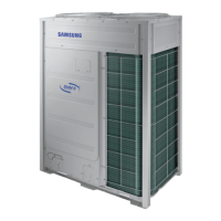
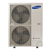
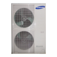
Categorizes outdoor units by type, capacity, and model names for various series.
Specifies indoor/outdoor unit combination limits, maximum indoor units, and connection ratios.
Lists key components and features for different models, including compressor, valves, and sensors.
Provides detailed technical specifications for outdoor units, including power, performance, dimensions, and operating ranges.
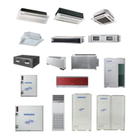
Details specifications for accessories and optional components like controllers, piping, and indoor units.
Lists essential tools and compatible accessories for refrigerant pipe installation and system maintenance.
Provides a structured guide for disassembling and reassembling the unit, starting with checking its condition.
Procedure for checking the unit's condition via the inspection window and main PBA for error codes and status.
Step-by-step instructions for safely removing the unit's front, back, and top panels.
Critical safety steps for disconnecting power, including removing covers and securing power connection box.
Detailed instructions for removing the compressor, including power terminal block access and soundproofing felt.
Procedure for compressor replacement, covering oil checks, vacuuming, and refrigerant quantity calculation.
Instructions for removing key components like the oil separator, accumulator, and receiver.
Procedure for removing the Hub PBA, including connector disconnection and screw fastening.
Steps for removing the Control Panel Assy, detailing how to turn it over and access internal components.
Instructions for removing the Inverter PBA, including unfastening screws and checking grease condition.
Procedure for removing DC Reactors and the EMI PBA, involving wire screws and connector disconnection.
Description of the check-up window on the PBA, detailing specific functions and connectors for diagnostics.
Guide to special service operations, including key inputs for different modes and PBA types.
Detailed troubleshooting steps and error code explanations for various system symptoms and failures.
Practical troubleshooting case studies covering common issues like electric discharge, pump down, and specific error codes.
Diagram and pin assignments for the Main PBA, covering Push button and DIP S/W configurations.
Diagram and pin assignments for the Main-HUB PBA, detailing AC and DC connectivity.
Diagram and pin assignments for the Inverter PBA, specifying connections for different models.
Diagram and pin assignments for the EMI PBA, illustrating connections for various series.
Diagram and pin assignments for the SUB-COMM module, detailing its connections.
Wiring diagram illustrating connections for AM080/100/120/200FXWA models.
Wiring diagram illustrating connections for AM300FXWA models.
Guidelines for electrical wiring work during installation, covering power, communication cables, and protection tubes.
Schematics showing refrigerant flow and component symbols for DVM S Water Heat Recovery systems.
Illustrates refrigerant flow paths for Cooling, Heating, and Heat Recovery operations.
Explanation of system functions, including P-h diagrams, refrigeration cycles, and control specifications.
Overview of system configuration using DIP switches and push buttons for setting selection.
Comprehensive list of field-configurable items and their purposes for system optimization.
Detailed explanation of outdoor unit option switches (SW51-SW58) and their settings.
Procedure for navigating and setting options using tact switches, with explanation of display indicators.
Description of specific applications like Auxiliary Heat Module and Mode Select Switch installation.
Guide to performing Auto Trial Operation, including preliminary checks, operational steps, and error handling.
Procedure for automatic refrigerant amount checking and troubleshooting judged results.
Explanation of the model naming convention, breaking down each code element.
| Brand | Samsung |
|---|---|
| Model | AM080FXWANR |
| Category | Air Conditioner |
| Language | English |