Do you have a question about the Samsung AM080JXVAFH/AZ and is the answer not in the manual?
Safety guidelines for servicing the unit, including part selection and connection integrity.
Handling electrostatic discharge and safety during PCB repair and measurements.
General safety rules for electrical operations, grounding, and preventing shocks.
Safety measures for handling refrigerant, including environmental and personal safety.
Safety guidelines for welding refrigerant pipes, emphasizing removal of flammable objects.
Procedures for adding refrigerant, calculating amounts, and safety during injection.
Step-by-step instructions for disassembling various outdoor unit components.
Explanation of the outdoor unit's diagnostic display codes and their functions.
Procedures for special service operations, including trial operation and refrigerant charging.
Guidance for diagnosing and resolving various operational issues and error codes.
Detailed diagram and component identification for the main assembly PCB.
Diagram and component identification for the main HUB PCB.
Diagram and component identification for the inverter PCB.
Diagram and component identification for the fan PCB.
Diagram and component identification for the EMI PCB.
Configuration details for DIP switches on the outdoor unit for various settings.
Guide to setting operational functions using tact switches and their descriptions.
Procedure for performing the automated system test and troubleshooting guide.
Method for automatically verifying the amount of refrigerant charge in the system.
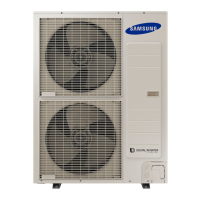
| Model | AM080JXVAFH/AZ |
|---|---|
| Brand | Samsung |
| Category | Air Conditioner |
| Cooling Capacity | 8.0 kW |
| Refrigerant | R410A |
| Power Supply | 220-240V, 50Hz |
| Outdoor Unit Dimensions (W x H x D) | 880 x 310 mm |





 Loading...