19
Refrigerating cycle temperature and pressure
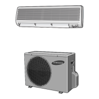
INDOOR UNIT
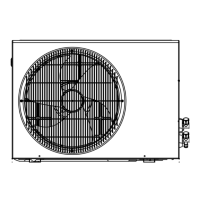
OUTDOOR UNIT
Heat
exchanger
(Evaporator)
Gas side
3-way valve
2-way valve
Liquid side
Capillary tube
Cooling
Gas leak check point
Cross fan
Heat
exchanger
(Condenser)
Propeller fan
Heating
Capillary tube
Check valve
Compressor
4-way valve
T
1
T
2
STD Pressure Piping Temp.(˚F) Use Temp. Condition (°F)
Operating Condition (psi)
T1 T2
Indoor Outdoor
3-WAY V/V DB WB DB WB
Standard 64~78 50~54 50~54 80 67 95 75
Cooling Max over load - 61~64 61~64 80 67 115 75
Low temp - 34~39 34~39 67 57 67 57
Standard 242~284 90~97 140~158 70 60 47 43
Heating Max over load - 97~104 149~167 80 - 75 65
Deice - 82~90 104~113 70 60 35 33
5. Refrigerating Cycle Block Diagram
1- 5/14/01 8:55 PM Page 19

 Loading...


