EasyManua.ls Logo

Samsung AQV12NSA Service Manual

Samsung AQV12NSA
92 pages
To Next Page IconTo Next Page
Page #1 background imageLoading...
Page #1 background image
Refer to the service manual in the GSPN(see the rear cover) for the more information.
AIR CONDITIONER THE FEATURE OF PRODUCT
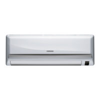
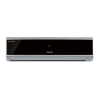
AQV09FCN, AQV12FCN, AQV09NSAN,AQV12NSAN
SPLIT-TYPE AIR CONDITIONER
INDOOR UNIT OUTDOOR UNIT
Basic : AQV12FA
Model
: AQV09NSA
AQV09FC
AQV12NSA
AQV12FC
Model Code : AQV09NSAN AQV09NSA
X
AQV09FCN AQV09FC
X
AQV12NSAN AQV12NSAX
AQV12FCN AQV12FCX
High Energy Efficiency BLDC
Air Conditioner
Simple Flat Grille Design
good'sleep Mode
: good'sleep Mode can help you sleep quickly and
soundly and wake up refreshed.
Multi Functional Cleaning System
: Silver Nano Health System and Deodorizing/
Catechin Filter are adopted.
Silence Mode
: When you use the "Silence Mode", you can
experience extremely quiet operation of your
air conditioner.
AQV09FCX, AQV12FCX, AQV09NSAX,AQV12NSAX

Table of Contents

Question and Answer IconNeed help?

Do you have a question about the Samsung AQV12NSA and is the answer not in the manual?

Samsung AQV12NSA Specifications

General IconGeneral
Cooling Capacity (Ton)1 Ton
Power Supply220-240V, 50Hz
TypeSplit AC
Cooling Capacity12000 BTU/h
Heating Capacity13000 BTU/hr

Summary

Product Overview and Features

Split-Type Air Conditioner Models

Identifies the available indoor and outdoor unit models and their basic specifications.

Key Product Features

Highlights main features like energy efficiency, design, and special operating modes.

Precautions and Safety

Air Conditioner Installation Guidelines

Covers safe installation practices, height requirements, and wiring protection.

Power Supply and Circuit Breaker Safety

Details safe electrical connections, circuit requirements, and cord handling.

Safe Operation Practices

Outlines rules for safe use, including avoiding liquids, keeping children clear, and ventilation.

Precautions (Continued)

Unit Disposal and Environmental Safety

Information on battery removal, dealer consultation for disposal, and recycling.

General Operational Guidelines

Covers storage orientation, child supervision, and measurement standards.

Product Specifications and Features

Detailed Product Features

Describes key features like BLDC efficiency, grille design, and special modes.

Technical Specifications Table

Detailed performance, electrical, and physical specifications for various models.

Model Comparison Table

Compares specifications between development and comparative air conditioner models.

Included Accessories List

Lists standard accessories provided with the indoor unit.

Outdoor Unit and Accessory Box Components

Lists accessories for the outdoor unit and items included in the accessory box.

Additional Accessory Items

Lists further accessories such as clamps, screws, and sealant.

Alignment and Adjustments

Test Mode Operation Procedure

Explains how to enter and utilize the test mode for unit checks.

Indoor Unit Error Codes and Diagnostics

Details error conditions indicated by indoor unit lamps and corresponding checks.

Outdoor Unit LED Error Indicators

Explains error codes displayed via LEDs on the outdoor unit and their meanings.

Setting Option Configuration Guide

Step-by-step instructions for configuring unit options via the remote control.

Verifying Option Settings and Test Run

Covers checking selected options and performing a test run after setup.

Remote Control Option Item Values

Table detailing specific values for remote control option items by model.

Disassembly and Reassembly

Required Tools for Disassembly

Lists essential tools needed for taking apart the unit.

Indoor Unit Front Grille Removal

Step-by-step guide to safely remove the front grille of the indoor unit.

Indoor Unit Internal Component Removal

Details steps for removing internal parts like the main PCB and drain tray.

Indoor Unit Heat Exchanger and Fan Motor Removal

Covers the process of removing the heat exchanger and fan motor.

Outdoor Unit Common Work and Panel Removal

Outlines initial steps for outdoor unit disassembly, including cover removal.

Outdoor Unit Cabinet Panel Detachment

Details the process of removing various cabinet side panels on the outdoor unit.

Outdoor Unit Control Assembly Disassembly

Instructions for removing the control assembly from the outdoor unit.

Outdoor Unit Fan, Heat Exchanger, and Valve Assembly Removal

Covers the removal of fan motor, heat exchanger, and valve assemblies.

Exploded Views and Parts List

Indoor Unit Exploded Diagram

Visual representation of indoor unit components with part number references.

Indoor Unit Parts List Details

Detailed list of indoor unit components, including part numbers and quantities.

Outdoor Unit Exploded Diagram

Visual representation of outdoor unit components with part number references.

Outdoor Unit Parts List Details

Detailed list of outdoor unit components, including part numbers and quantities.

Control In Assembly Details

Exploded view and parts list for the control in assembly.

Control Out Assembly Diagram

Exploded view of the control out assembly with component references.

Control Out Assembly Parts List

Detailed list of components for the control out assembly.

Electrical Parts List

Indoor Main PCB Component Details

Lists electrical components and their specifications for the indoor main PCB.

Indoor Main PCB Component Details (Continued)

Further listing of electrical components for the indoor main PCB.

Indoor Sub PCB and Display PCB Components

Details electrical components for the indoor sub PCB and display PCB.

Outdoor Main PCB Component Details

Lists electrical components and their specifications for the outdoor main PCB.

Outdoor Main PCB Component Details (Continued)

Further listing of electrical components for the outdoor main PCB.

Outdoor EMI PCB Component Details

Details electrical components for the outdoor EMI PCB.

Wiring Diagram

Indoor Unit Wiring Schematic

Illustrates electrical connections and component interrelationships within the indoor unit.

Outdoor Unit Wiring Schematic

Illustrates electrical connections and component interrelationships within the outdoor unit.

Schematic Diagram

Indoor Unit Circuit Schematic

Detailed circuit diagram for the indoor unit, illustrating component logic and flow.

Outdoor Unit Circuit Schematic

Detailed circuit diagram for the outdoor unit, illustrating component logic and flow.

Circuit Descriptions

Indoor Unit PCB Circuit Details

Explanation of the circuit blocks and functions on the indoor unit's main PCB.

Outdoor Unit PCB Circuit Details

Explanation of the circuit blocks and functions on the outdoor unit's main PCB.

Refrigerating Cycle Diagram

Refrigerant Flow Overview

Illustrates the path of refrigerant through the air conditioner system during operation.

PCB Diagram

Indoor PCB Component Identification

Visual layout of the indoor PCB with numbered components and a corresponding legend.

Outdoor PCB Component Identification

Visual layout of the outdoor PCB with numbered components and a corresponding legend.

Operating Instructions

Indoor Unit Component Identification

Labels and describes the main parts and indicators of the indoor unit.

Outdoor Unit Component Identification

Identifies key external parts of the outdoor unit for reference.

Remote Control Operation Guide

Explains the functions of all buttons and display elements on the remote control.

Basic Operating Modes (Auto, Cool, Heat)

Describes how to use the Auto, Cool, and Heat modes with the remote control.

Additional Operating Modes (Dry, Fan, Turbo, Sleep)

Explains the usage of Dry, Fan, Turbo, and good'sleep modes.

Troubleshooting Guide

Initial Checks and Common Symptoms

Lists basic checks and explains common operational behaviors that are not malfunctions.

Troubleshooting: No Power Error

Provides a step-by-step guide for diagnosing and resolving 'no power' issues.

Troubleshooting: Outdoor Unit Power Supply Error

Offers a diagnostic flowchart for outdoor unit power supply issues.

Troubleshooting: Up/Down Louver Motor Failure

Guides users through diagnosing and fixing issues with the louver motor.

Troubleshooting: Outdoor Fan Error

Provides a diagnostic flowchart for common outdoor fan errors.

Troubleshooting: Total Current Trip Error

Outlines steps to diagnose and resolve total current trip errors.

Troubleshooting: Incorrect Mode Operation

Addresses issues where the unit operates in the wrong heating/cooling mode.

Troubleshooting: Outdoor Temperature Sensor Error

Guides diagnosis and resolution for outdoor temperature sensor faults.

Troubleshooting: Discharge Temperature Sensor Error

Provides diagnostic steps for discharge temperature sensor faults.

Troubleshooting: Coil Temperature Sensor Error

Outlines the process for diagnosing and fixing coil temperature sensor issues.

Troubleshooting: Fan Error

Provides diagnostic steps for fan errors, including checking for locks and correct wiring.

Troubleshooting: DC-Link Voltage Sensor Error

Guides diagnosis and resolution for errors related to the DC-Link voltage sensor.

Troubleshooting: Over Current (O.C.) Error

Outlines diagnostic steps for Over Current errors, focusing on resistance and compressor checks.

Troubleshooting: Communication Error

Provides a diagnostic flowchart for communication failures between units.

Troubleshooting: Compressor Start Error

Guides diagnosis and resolution for compressor start failures.

Troubleshooting: Compressor Lock Error

Outlines diagnostic steps for compressor lock errors, checking resistance and insulation.

Troubleshooting: DC Link Voltage Error

Provides diagnostic steps for DC Link over/low voltage errors.

Troubleshooting: Remote Control Issues

Addresses problems with the remote control not receiving signals.

Troubleshooting: Other System Errors

Covers miscellaneous issues like zero cross signal and capacity mismatch.

PCB Inspection and Troubleshooting

Pre-Inspection Guidelines for PCBs

Safety and preparation notes before inspecting PCBs.

Indoor PCB Inspection Procedures

Step-by-step methods for inspecting the indoor unit's PCB for faults.

Outdoor PCB Inspection Procedures

Step-by-step methods for inspecting the outdoor unit's PCB for faults.

Component Inspection Methods

Sensor and Motor Resistance Checks

Details how to measure resistance for key sensors and motors.

Block Diagram

Indoor Unit System Block Diagram

Illustrates the functional blocks and data flow within the indoor unit's control system.

Indoor Unit PCB Block Diagram View

A visual representation of the indoor unit's PCB layout and major functional areas.

Outdoor Unit System Block Diagram

Illustrates the functional blocks and data flow within the outdoor unit's control system.

Outdoor Unit PCB Block Diagram View

A visual representation of the outdoor unit's PCB layout and major functional areas.

Reference Sheet

Air Conditioner Model Name Convention

Explains the structure and meaning of different parts of the air conditioner's model name.

Low Refrigerant Pressure Charts

Graphs illustrating refrigerant pressure variations under different temperature conditions.

Unit Conversion Factors (Power/Heat)

Table providing conversion values for various units related to power and heat.

Troubleshooting Q&A (Non-Malfunctions)

Frequently asked questions and answers addressing common operational issues not related to unit failure.

Troubleshooting Q&A (Continued)

Additional Q&A entries covering smells, starting issues, operation interruptions, and remote control problems.

Installation Guidelines and Considerations

Information regarding installation procedures, placement, and environmental factors.

Maintenance and Cleaning

Cleaning the Air Filter and Front Grille

Step-by-step instructions for cleaning the air conditioner's filters and exterior grille.

Cleaning Optional Filters

Instructions for cleaning the deodorizing and bio filters, which are optional components.

Installation Procedures

Pre-Installation Considerations

Guidelines on selecting the location and preparing for installation.

Installation Steps and Requirements

Detailed steps for installing the unit, including drilling, piping, testing, and electrical work.

Air-Purge Procedure for Installation

Detailed steps and diagrams for purging air from the system during installation.

"Pump Down" Procedure for Relocation

Instructions for performing a pump-down operation, often required before unit relocation.

Service and Support Information

Global Service Partner Network (GSPN)

Contact details and website links for Samsung's global service network.

Related product manuals