Do you have a question about the Samsung AQV12NSAN and is the answer not in the manual?
Guidelines for safe and correct service procedures, including part replacement and harness connection.
Safety measures related to static electricity and personal safety during repair.
General safety guidelines to prevent electric shock, fire, and damage during operation and repair.
Details on product features like good' sleep Mode, Catechin Filter, Silver Nano Evaporator, and MPI Mode.
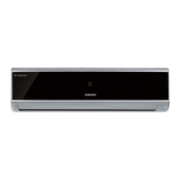
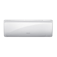
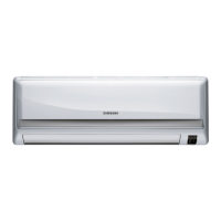
Highlights design and chassis changes between basic and new models for indoor and outdoor units.
Table comparing performance, capacity, size, and other specifications for AQV09UGA and AQV12UGA models.
Lists included accessories like remote control and plate hanger, and optional items like filters.
Lists essential tools required for disassembling the unit, such as screwdrivers and spanners.
Step-by-step procedure for disassembling the indoor unit, covering parts like the front panel and tray drain.
Detailed steps for disassembling the outdoor unit, including removing covers, plates, and internal components.
Step-by-step guide on how to enter and configure option settings using the remote control.
Details various error codes displayed by the unit and provides methods for checking and diagnosing the faults.
Guides users through troubleshooting common issues based on symptoms like communication errors, sensor failures, and motor problems.
Outlines procedures for inspecting Printed Circuit Boards (PCBs) including pre-checks, general procedures, and detailed indoor/outdoor inspections.
Instructions for inspecting key components like temperature sensors, fan motors, and stepping motors using a tester.
Provides an exploded view diagram and a comprehensive list of parts for the indoor unit.
Presents an exploded view diagram and a detailed list of parts for the outdoor unit.
Details the parts and quantities for the control assembly, referencing specific model codes.
Shows the high-level functional blocks and interconnections for the Ass'y Control In.
Identifies connectors and their functions on the indoor main PCB (DB93-07430B).
Details the connectors and signals for the indoor display PCB (DB93-06984C).
Shows connections for the outdoor main PCB (DB93-07108C/DB93-07108D).
Illustrates the components and connections for the outdoor EMI PCB (DB93-07050A).
Comprehensive list of electronic components used on the main PCB, including code numbers, descriptions, and specifications.
Illustrates the wiring connections and component layout for the indoor unit.
Shows the electrical wiring and connections between components in the outdoor unit.
Provides a detailed schematic of the indoor unit's electronic circuits, including power, control, and sensor connections.
Details the circuitry related to the display unit, showing component connections and options.
Presents the schematic diagram for the outdoor unit, illustrating modules like AC Zero Cross, BLDC Motor Drive, Communication, and SMPS.
Illustrates the flow of refrigerant through the air conditioning system's components.
Explains the coding system used for model names, breaking down each character's meaning.
Displays charts showing the relationship between outdoor temperature, indoor temperature, and refrigerant pressure.
| Type | Split system |
|---|---|
| Compressor type | Rotary |
| Hose length (max) | 15 m |
| Remotely operated | Yes |
| Cooling capacity (max) | 11942 BTU/h |
| Dehumidifying capacity | 1.4 l/h |
| Heating capacity (max) | 13649 BTU/h |
| Cooling capacity in watts (max) | 3500 W |
| Heating capacity in watts (max) | 4000 W |
| Cooling energy efficiency (EER, W/W) | 3.30 |
| Heating energy efficiency (COP, W/W) | 3.61 |
| Indoor unit type | Wall-mountable |
| Airflow | 480 m³/h |
| Power requirements | 220-240V/50Hz |
| Power consumption (typical) | 1060 W |
| Weight | 9000 g |
|---|---|
| Dimensions (WxDxH) | 825 x 189 x 285 mm |