Do you have a question about the Samsung AQV12VBCN and is the answer not in the manual?
Guidelines for safe and proper installation of the air conditioner, including placement and wiring.
Instructions for connecting the air conditioner to a suitable power supply and circuit breaker.
Precautions for safe operation, maintenance, and child safety during air conditioner use.
Procedures and environmental considerations for safely disposing of the air conditioner unit.
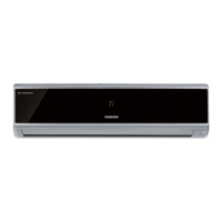
Details on key features like High Energy Efficiency BLDC, Luxury Half Mirror Design, and special modes.
Detailed technical specifications including capacity, performance, power, and dimensions for different models.
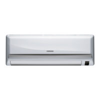
Comparison of design and key specifications between AQV09VBC and AQV12VBC models.
List of included accessories and their specifications for indoor and outdoor units.
Procedure for entering and operating the Test Mode for initial checks and diagnostics.
Table detailing indoor unit LED error codes, their explanations, and potential causes.
Guide to interpreting outdoor unit LED indicator patterns for error diagnosis.
Step-by-step instructions for configuring unit options using the remote control.
List of essential tools required for the disassembly and reassembly procedures.
Detailed procedure for disassembling the front panel and filter of the indoor unit.
Procedure for common work and detaching the cabinet front and control plates of the outdoor unit.
Exploded diagram and parts list for the indoor unit components.
Exploded diagram for the outdoor unit components.
Exploded diagram and parts list for the 'Ass'y Control In' assembly.
Exploded diagram for the 'Ass'y Control Out' assembly.
List of electrical components for the Main PCB, including location, code, description, and specification.
List of electrical components for the Sub PCB, including location, code, and specification.
List of electrical components for the Outdoor PCB, including location, code, and specification.
List of electrical components for the EMI PCB, including location, code, specification, and quantity.
Wiring diagram illustrating the electrical connections within the indoor unit.
Wiring diagram showing the electrical connections for the outdoor unit and its components.
Schematic diagram detailing the electronic circuit layout of the indoor unit.
Schematic diagram illustrating the electronic circuit design of the outdoor unit.
Explanation of the functions of various circuit blocks on the indoor unit's PCB.
Description of circuit blocks and their functions within the outdoor unit's PCB.
Diagram illustrating the refrigerant flow through the indoor and outdoor units during operation.
Visual layout of components on the indoor unit's Printed Circuit Board (PCB).
Visual representation of the component layout on the outdoor unit's Printed Circuit Board (PCB).
Identification of the main parts of the indoor unit with descriptive labels.
Identification of the main parts of the outdoor unit with descriptive labels.
Detailed explanation of the remote control buttons, functions, and display indicators.
Instructions for basic operation modes: Auto, Cool, and Heat, including fan speed settings.
Explanation of special operating functions like good'sleep Mode, Silence Mode, and MPI Mode.
Initial checks for common operational issues before diagnosing specific faults.
Step-by-step troubleshooting guides for various unit errors and symptoms.
Methods for inspecting PCBs, identifying components, and checking connections.
Methods for inspecting main components like temperature sensors and motors using a tester.
Block diagram illustrating the functional modules and signal flow of the indoor unit.
Block diagram showing the functional modules and signal flow of the outdoor unit.
Guide for decoding model names based on product division, classification, and version codes.
Charts showing refrigerant pressure distribution based on indoor and outdoor temperatures.
Conversion table for pressure and capacity units (W, cal/s, kcal/h, Btu/h, HP, kg.m/s, lb-m/s).
Frequently asked questions and answers regarding common non-trouble issues like weak cooling or water leakage.
Guidelines for installation, relocation, ensuring ventilation, and specific installation procedures.
Step-by-step instructions for cleaning the indoor unit, air filter, anti-allergy, and deodorizing filters.
Diagrams for air-purge and procedures for 'pump down' during installation or relocation.
| Cooling Capacity | 12000 BTU/h |
|---|---|
| Refrigerant | R410A |
| Power Supply | 220-240V, 50Hz |
| Type | Split System |
| Operating Temperature (Cooling) | 18°C to 43°C |