Do you have a question about the Samsung AQV18FA and is the answer not in the manual?
Guidelines for proper installation to prevent hazards like fire, water leakage, or electric shock.
Instructions for safe power supply connection and circuit breaker usage to avoid hazards.
Safety precautions to follow during the operation of the air conditioner.
Procedures for safe disposal of the air conditioner and its components, emphasizing environmental responsibility.
General precautions and guidelines, including handling, supervision of users, and measurement standards.
Highlights key features like high energy efficiency, design, sleep mode, cleaning system, and silence mode.
Detailed technical specifications for different models, including capacity, performance, power, and dimensions.
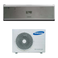
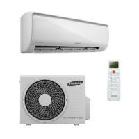
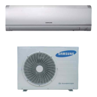
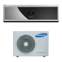
Compares specifications and design elements of different development models, showing side-by-side differences.
Lists and details the various accessories and optional items included with the air conditioner, with code numbers and quantities.
Instructions on how to enter and operate the test mode for checking air conditioner functionality after installation.
Details error codes displayed on the indoor unit and the corresponding check points for troubleshooting.
Explains the LED error codes on the outdoor unit and provides methods for checking and diagnosing issues.
Step-by-step guide on how to set various options using the remote control for customized operation.
Lists the essential tools required for the disassembly and reassembly procedures.
Step-by-step instructions with images for disassembling the indoor unit's front grille and related parts.
Instructions for disassembling the outdoor unit, starting with common work like removing the cover control and cabinet parts.
Provides an exploded view diagram of the indoor unit, showing the location of various parts.
Presents an exploded view diagram for the outdoor unit, illustrating the arrangement of its components.
Provides an exploded view and parts list specifically for the "Ass'y Control In" component.
Shows an exploded view of the "Ass'y Control Out" assembly, indicating the placement of its components.
Lists electrical components and their details for the main PCB of the indoor unit.
Continues the list of electrical components for the main PCB, detailing resistors and capacitors.
Continues the list of electrical components for the main PCB, covering fuses, connectors, and other parts.
Lists electrical components for the indoor sub PCB, including diodes, ICs, and resistors.
Details the electrical components found on the display PCB, such as LEDs, switches, and connectors.
Lists electrical components for the outdoor main PCB, including diodes, transistors, and ICs.
Continues the list of electrical components for the outdoor main PCB, detailing resistors and capacitors.
Continues the list of electrical components for the outdoor main PCB, covering capacitors, varistors, and relays.
Continues the list of electrical components for the outdoor main PCB, including connectors, LEDs, and sensors.
Lists electrical components for the outdoor EMI PCB, including varistors, capacitors, and surge absorbers.
Lists electrical components for the outdoor EMI PCB for a different model, covering similar component types.
Details the electrical components on the outdoor display PCB, such as diodes, LEDs, switches, and connectors.
Provides the wiring diagram for the indoor unit, illustrating connections between components and PCBs.
Presents the wiring diagram for the outdoor unit, showing electrical connections and component layouts for 18K and 24K models.
Displays the schematic diagram for the indoor unit, detailing the electronic circuit layout and connections.
Shows the schematic diagram for the outdoor unit, illustrating the electronic circuit design and component interconnections.
Describes the functional blocks and circuits on the indoor unit's PCB, highlighting key modules.
Describes circuit descriptions for the outdoor unit's PCB, including signal flows and modules.
Illustrates the refrigerating cycle of the air conditioner, showing the flow of refrigerant between indoor and outdoor units.
Shows a physical diagram of the indoor unit's PCB with numbered component locations.
Displays a physical diagram of the outdoor unit's PCB with numbered component locations.
Identifies and labels the main parts of the indoor unit, including the air filter and controls.
Identifies and labels the main parts of the outdoor unit, such as air inlet, outlet, and connection valve.
Explains the functions of the buttons and indicators on the wireless remote control.
Details the basic functions of the air conditioner, such as Auto, Cool, and Heat modes, including fan speed settings.
Explains applied functions like Turbo and Good Morning modes, and their operation.
Provides initial checks for common issues, including voltage, cable connections, and operational symptoms.
Troubleshooting flowcharts for various fault symptoms, covering power, fan, sensor, and communication errors.
Guides for inspecting PCBs, including pre-inspection notices and detailed procedures for indoor and outdoor units.
Details inspection methods for main components like temperature sensors, fan motors, and stepping motors.
Shows the block diagram for the indoor unit, illustrating the control system and signal flow between components.
Illustrates the block diagram for the outdoor unit, showing control logic and connections to sensors, compressor, and fan.
Explains the coding system used for model names, defining each character's significance.
Provides charts showing refrigerant pressure distribution based on indoor and outdoor temperatures for different models.
Presents conversion tables for pressure and capacity units (W, cal/s, kcal/h, Btu/h, HP, kg.m/s, lb-m/s).
Addresses common non-trouble issues and provides answers, such as weak cooling or floor flooding.
Instructions for cleaning the air conditioner and its filters, emphasizing regular maintenance for optimal performance.
Outlines the installation steps, including location selection, wall drilling, unit fixing, and pipe connections.
Step-by-step procedure for air purging using a vacuum pump, crucial for preventing gas leaks.
| Brand | Samsung |
|---|---|
| Model | AQV18FA |
| Category | Air Conditioner |
| Language | English |