Do you have a question about the Samsung AQV18VBEX and is the answer not in the manual?
Safety guidelines for installing the air conditioner unit.
Proper electrical connection and safety for power supply.
Safety precautions to follow while the air conditioner is operating.
Guidelines for environmentally responsible disposal of the air conditioner.
Additional general precautions and safety notes for users.
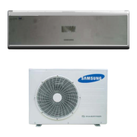
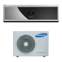
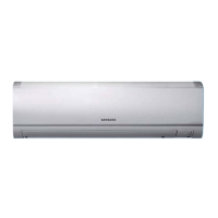
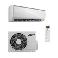
Highlights the key features and benefits of the air conditioner.
Detailed technical specifications for cooling, heating, and performance.
Comparison of specifications between different product models.
Lists included accessories and optional components for the product.
Procedure for operating the unit in test mode for diagnostics.
Explains error codes displayed on the indoor unit and their checks.
Describes error indicators on the outdoor unit and troubleshooting steps.
Guide on how to set various operational options using the remote control.
Lists the essential tools required for disassembly and reassembly procedures.
Step-by-step instructions for disassembling the indoor unit.
Step-by-step instructions for disassembling the outdoor unit.
Visual breakdown and list of parts for the indoor unit.
Visual breakdown and list of parts for the outdoor unit.
Detailed parts list for the 'Ass'y Control In' component.
Detailed parts list for the 'Ass'y Control Out' component.
Comprehensive list of electrical components on the indoor main PCB.
Comprehensive list of electrical components on the outdoor main PCB.
List of electrical parts for the outdoor display PCB.
Electrical wiring diagram for the indoor unit.
Electrical wiring diagram for the outdoor unit.
Electrical schematic diagram for the indoor unit.
Electrical schematic diagram for the outdoor unit.
Detailed description of the circuits on the PCBs.
Diagram illustrating the refrigerant flow and cycle of the air conditioner.
Visual layout of components on the indoor PCB.
Visual layout of components on the outdoor PCB.
Identification of the various parts and indicators on the indoor unit.
Explanation of the remote control buttons and display indicators.
Instructions on operating basic functions like Auto, Cool, Heat modes.
Initial checks to perform before diagnosing a problem with the unit.
Troubleshooting guide based on specific operational symptoms and errors.
Procedures for inspecting and testing PCBs for faults.
Methods for inspecting and testing key components of the unit.
High-level functional block diagram of the indoor unit system.
High-level functional block diagram of the outdoor unit system.
Guide to understanding the model naming convention and its components.
Charts showing refrigerant pressure variations under different conditions.
Conversion table for pressure and capacity units.
Frequently asked questions and answers regarding common non-trouble issues.
Instructions for cleaning the unit and replacing air filters.
Guidelines and procedures for installing the air conditioner unit.
Visual guide for the indoor and outdoor unit installation process.
| Brand | Samsung |
|---|---|
| Model | AQV18VBEX |
| Category | Air Conditioner |
| Language | English |