Do you have a question about the Samsung AQV18PSBN and is the answer not in the manual?
Guidance on proper installation of the air conditioner, including safety regulations and placement.
Step-by-step guide for disassembling and reassembling the outdoor unit.
Guide to interpreting error codes and checking points for indoor and outdoor units.
Diagnostic procedures based on observed symptoms for indoor and outdoor units.
Diagrams and pin assignments for indoor unit PCBs.
Diagrams and pin assignments for outdoor unit PCBs.
Wiring diagrams for indoor unit connections.
Wiring diagrams for outdoor unit connections.
Schematic diagrams for indoor unit circuitry.
Schematic diagrams for outdoor unit circuitry.
Procedure for connecting refrigerant pipes and purging the circuit.
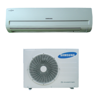
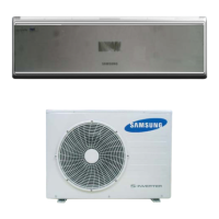
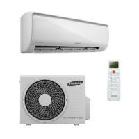
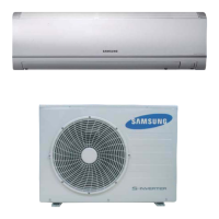
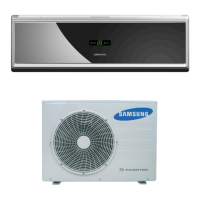
| Indoor unit type | Wall-mountable |
|---|---|
| Indoor unit weight | 11000 g |
| Indoor unit dimensions (WxDxH) | 1065 x 230 x 298 mm |
| Indoor unit noise level (high speed) | 40 dB |
| Outdoor unit weight | 38000 g |
| Outdoor unit noise level | 53 dB |
| Outdoor unit dimensions (WxDxH) | 790 x 285 x 545 mm |
| Type | Split system |
| Hose length (max) | 30 m |
| Remotely operated | Yes |
| Cooling capacity (max) | - BTU/h |
| Air conditioner functions | cooling, heating |
| Cooling capacity in watts (max) | 5000 W |
| Heating capacity in watts (max) | 6000 W |
| Cooling energy efficiency (EER, W/W) | 3.4 |
| Heating energy efficiency (COP, W/W) | 3.61 |
| Airflow | 828 m³/h |
| Power requirements | 220 - 240V, 50Hz |
| Power consumption (cooling) (max) | 1470 W |
| Power consumption (heating) (max) | 1660 W |