Do you have a question about the Samsung AR09AXKAAWKNEU and is the answer not in the manual?
Guidance on proper installation procedures for the air conditioner, including safety measures.
Information regarding the safe connection of power supply and the use of circuit breakers.
Instructions and warnings related to the safe operation of the air conditioner.
Guidelines for the environmentally responsible disposal of the air conditioner.
Miscellaneous safety warnings and important notes for handling the unit.
Overview of the key features and functionalities of the air conditioner.
Detailed technical specifications, performance data, and dimensions of the product.
A comparison of specifications between different models.
List and details of accessories and optional components available for the unit.
Procedure for entering and operating the unit in test mode for diagnostics.
Guide to interpreting error codes displayed on the unit and troubleshooting steps.
Instructions for configuring various operational options using the remote control.
List of essential tools required for disassembling and reassembling the unit.
Step-by-step instructions for disassembling the indoor unit components.
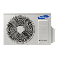
Step-by-step instructions for disassembling the outdoor unit components.
Details and component list for ASSY KIT CODE DB92-05034G.
Details and component list for ASSY KIT CODE DB92-05032F.
Schematic diagram illustrating the wiring connections for the indoor unit.
Schematic diagram illustrating the wiring connections for the outdoor unit.
Layout and connector identification for the indoor unit's main PCB.
Layout and connector identification for the outdoor unit's main PCB.
Layout and connector identification for the display PCB.
Instructions and illustrations for connecting wires to indoor unit terminal blocks.
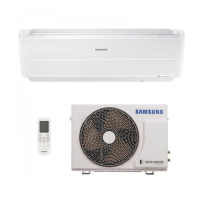
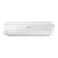
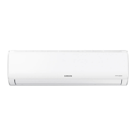
Identification and description of the main parts of the indoor unit.
Explanation of the buttons and display indicators on the wireless remote control.
Basic checks to perform before diagnosing specific issues with the air conditioner.
Procedure for diagnosing and resolving communication errors between units.
Troubleshooting steps for errors related to the indoor temperature sensor.
Diagnosing and resolving errors related to the indoor fan motor speed detection.
Troubleshooting steps for errors related to the outdoor temperature sensor.
Diagnosing and resolving errors related to the outdoor condenser temperature sensor.
Troubleshooting steps for errors related to the outdoor discharge temperature sensor.
Resolving errors indicating prohibited operation conditions based on environmental factors.
Troubleshooting steps for EEPROM or OTP errors, often related to data corruption.
Diagnosing and resolving errors related to the outdoor fan motor.
Troubleshooting steps for errors occurring during the compressor's start-up phase.
Resolving errors related to compressor wire connection or rotation.
Troubleshooting steps for AC input current limit or sensor errors.
Diagnosing and resolving IPM Over Current (O.C.) errors.
Troubleshooting steps when the outdoor unit shows no power.
Resolving issues where the louver motors (up/down, left/right) do not operate.
Troubleshooting steps when the remote control is not received by the unit.
Diagnosing and resolving errors encountered during the Smart Install mode.
Troubleshooting steps for outdoor OLP (Over Load Protection) over temperature errors.
Schematic diagram showing the functional blocks and connections of the indoor unit.
Schematic diagram showing the functional blocks and connections of the outdoor unit.
Data on low refrigerant pressure distribution under various temperature conditions.
Chart relating pressure values to cooling/heating capacity.
Frequently asked questions and answers for common non-trouble issues.
Procedures for cleaning the unit's sensors, filters, and panels.
Detailed steps and guidelines for the correct installation of the air conditioner.
Visual diagrams illustrating the installation process, including piping and air-purge.
Index for understanding model names and their corresponding specifications.
| Brand | Samsung |
|---|---|
| Model | AR09AXKAAWKNEU |
| Category | Air Conditioner |
| Language | English |