EasyManua.ls Logo

Samsung AR36BSHUMGMNCV User Manual

Samsung AR36BSHUMGMNCV
73 pages
To Next Page IconTo Next Page
Page #1 background imageLoading...
Page #1 background image
AIR CONDITIONER CONTENTS
SYSTEM AIR CONDITIONER
SINGLE for North America (R-410A, Heat Pump)
1. Precautions
2. Product Speciѣcations
3. Disassembly and Reassembly
4. Troubleshooting
5. PCB Diagram and Parts List
6. Wiring Diagram
7. Reference Sheet
INDOOR UNIT OUTDOOR UNIT
AR36BSHUMGMNCV AR36BSHUMGMXCV

Table of Contents

Question and Answer IconNeed help?

Do you have a question about the Samsung AR36BSHUMGMNCV and is the answer not in the manual?

Samsung AR36BSHUMGMNCV Specifications

General IconGeneral
Cooling Capacity (kW)3.5 kW
RefrigerantR32
Power Supply220-240V, 50Hz
InverterYes
FeaturesSleep Mode

Summary

1. Precautions

1-1. Precautions for the Service

General guidelines for performing service procedures.

1-2. Precautions for Static Electricity

Warnings about handling PCBs and preventing static discharge.

1-3. Safety Precautions

Essential safety measures for electrical work and handling.

2. Product Specifications

2-1. Product Specifications

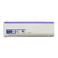
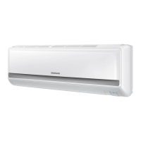
Detailed technical specifications of the air conditioner unit.

2-2. Specifications of Optional Items

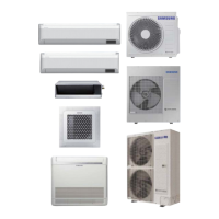
Details on optional accessories and their specifications.

3. Disassembly and Reassembly

Necessary Tools

List of essential tools required for disassembly and reassembly.

4. Troubleshooting

4-1. Setting Indoor Unit Address and Option

Procedure for setting indoor unit address and installation options.

5. PCB Diagram and Parts List

5-1. Indoor Unit Main PBA

Diagram and parts list for the indoor unit's main circuit board.

5. PCB Diagram and Parts List

5-2. Indoor Unit Sub PBA

Diagram and parts list for the indoor unit's sub circuit board.

5. PCB Diagram and Parts List

5-3. Outdoor Unit Main PBA

Diagram and parts list for the outdoor unit's main circuit board.

5. PCB Diagram and Parts List

5-4. Outdoor Unit Inverter PBA

Diagram and parts list for the outdoor unit's inverter circuit board.

5. PCB Diagram and Parts List

5-5. Outdoor Unit EMI PBA

Diagram and parts list for the outdoor unit's EMI circuit board.

6. Wiring Diagram

6-1. Indoor Unit

Wiring schematic for the indoor unit.

6. Wiring Diagram

6-2. Outdoor unit

Wiring schematic for the outdoor unit.

7. Reference Sheet

7-1. Index for Model Name

Index for identifying models based on their naming convention.

7. Reference Sheet

7-2. Refrigerating Cycle Diagram

Diagram illustrating the refrigerant flow in the system.

Related product manuals