EasyManua.ls Logo

Samsung AS09HPBN User Manual

Samsung AS09HPBN
82 pages
To Next Page IconTo Next Page
Page #1 background imageLoading...
Page #1 background image
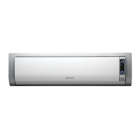
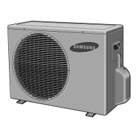
AS09HPBN
AS12HPBN
Precautions 1
Product Specifications 2
Operating Instructions & Installation 3
Disassembly and Reassembly 10
Refrigerating Cycle Diagram 16
Feature & Operation 27
Set Up the Model Option 46
Troubleshooting 49
Exploded Views and Parts List 62
Block Diagram 67
PCB Diagram 68
Wiring Diagram 77
Schematic Diagram 79
CONTENTS
DB98_20801A(1)_co 12/24/04 10:42 AM Page 1

Other manuals for Samsung AS09HPBN

Questions and Answers:

Samsung AS09HPBN Specifications

General IconGeneral
Cooling Capacity9000 BTU/h
RefrigerantR410A
Power Supply220-240V, 50Hz
EER3.21
COP3.61
Operating Temperature (Cooling)18°C to 43°C
Net Weight (Outdoor Unit)26 kg

Summary

Precautions

Product Specifications

Operating Instructions & Installation

View of the Unit

Diagrams and labels identifying components of the indoor and outdoor units.

Air Conditioner and Accessories

Lists all included and optional accessories required for installation.

Installation Procedures

Step-by-step guide for installing the air conditioner, including pre-installation checks.

Installation Diagrams and Procedures

Details air-purge, refrigerant refill, and pump-down procedures for installation.

Disassembly and Reassembly

Indoor Unit Disassembly

Step-by-step guide for safely disassembling the indoor unit for maintenance.

Outdoor Unit Disassembly

Step-by-step guide for safely disassembling the outdoor unit for maintenance.

Refrigerating Cycle Diagram

Refrigerating Cycle Diagram

Visual representation of the refrigerant flow between indoor and outdoor units.

Refrigerant Cycle Characteristics

Data on capacity, power, air volume, and noise distributions under various conditions.

R410A Usage Cautions

Essential safety and handling precautions when working with R410A refrigerant.

Feature & Operation

Remote Control Functions

Explains the purpose and operation of each button on the remote control.

Details of Proper Operation

Explains various operating modes like AUTO, COOL, HEAT, DRY, TURBO, and SLEEP.

Control and Protection Features

Details indoor fan control, overload protection, low temperature release, and defrost functions.

Auto Clean and Test Operation

Describes the auto clean function and how to perform a test operation for verification.

Set Up the Model Option

Setting Option Setup Method

Procedure for entering setup mode and configuring unit options via remote control.

Troubleshooting

Initial Checks and Common Issues

Basic troubleshooting steps and common non-malfunction symptoms to check first.

Fault Diagnosis by Symptom

Guides for diagnosing issues based on error codes and operational symptoms.

Sensor Failure Diagnosis

Troubleshooting steps for diagnosing room and pipe temperature sensor failures.

Component Failure Diagnosis

Troubleshooting guides for common component failures like fan, louver motor, and outdoor unit.

Exploded Views and Parts List

Indoor Unit Parts

Exploded view diagrams and corresponding parts list for the indoor unit.

Outdoor Unit Parts

Exploded view diagrams and corresponding parts list for the outdoor unit.

Control Assembly Parts

Parts list specifically for the control assembly components.

Block Diagram

System Block Diagram

Illustrates the overall system architecture, including signal flow and component interconnections.

PCB Diagram

Main PCB Diagram

Detailed layout and component identification for the main printed circuit board.

Melody PCB Diagram

Diagram showing the layout of the melody (buzzer/speaker) PCB.

Display PCB Diagram

Diagram showing the layout of the display unit PCB.

Module PCB Diagram

Diagram showing the layout of the module PCB.

Wiring Diagram

Indoor Unit Wiring

Shows the electrical connections and wire routing within the indoor unit.

Outdoor Unit Wiring

Shows the electrical connections and wire routing within the outdoor unit.

Schematic Diagram

Indoor Unit Schematic

Detailed electronic schematic illustrating the circuitry of the indoor unit.

Related product manuals