18
Troubleshooting (Continued)
ΙΙΙΙΙΙ
3. When the Outdoor Unit Does Not Operate - Initial Diagnosis
3. When the Outdoor Unit Does Not Operate - Initial Diagnosis
1) Checklist :
(1) Is input voltage normal? (voltage rating within ±10% range)
(2) Is the set temperature of the remote control higher than room temperature in the Cool mode?
(3) Is the POWER IN connector (CN78) linked correctly?
(4) Is the outdoor unit properly connected with the terminal black connector(Refer to page 5)?
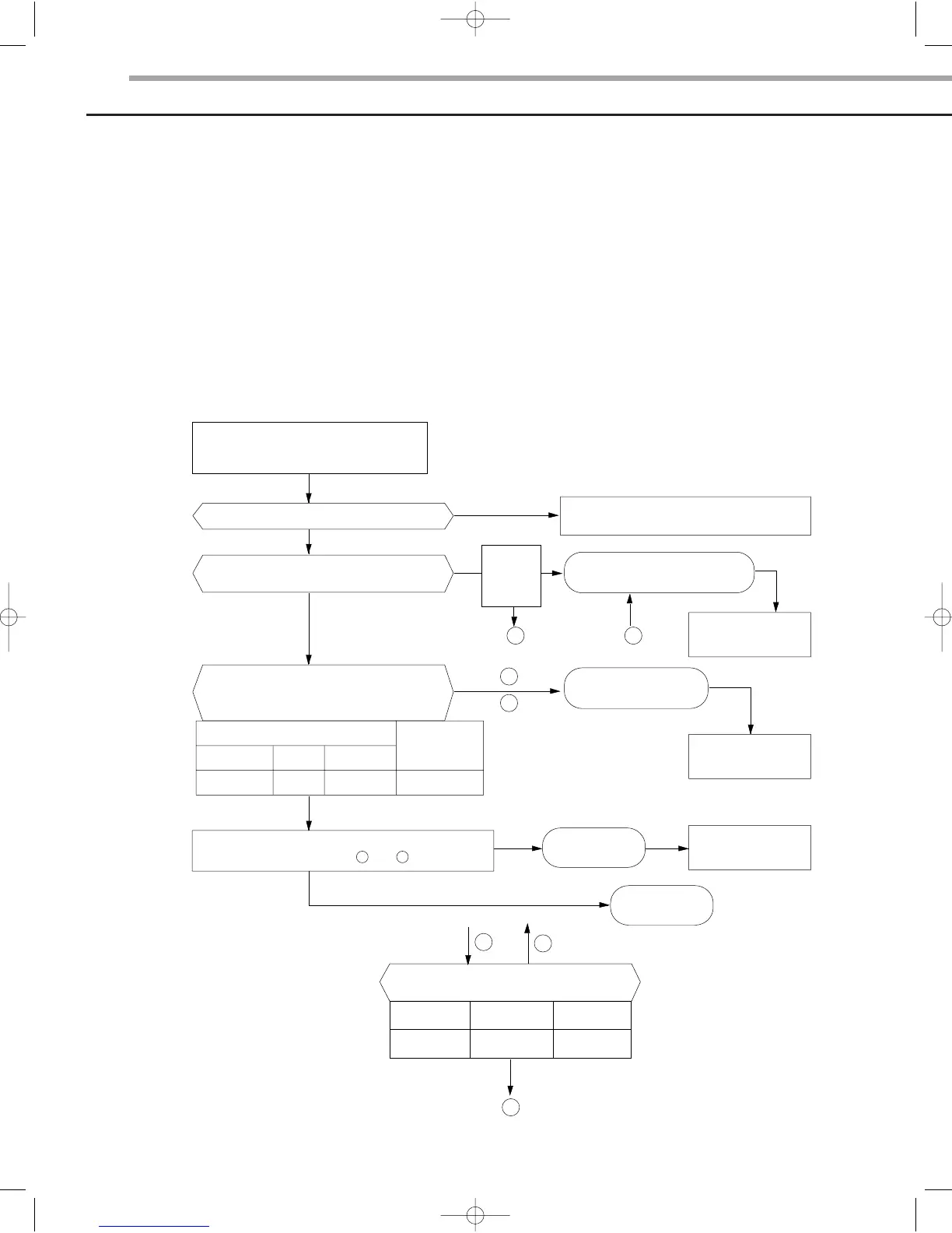
2) Troubleshooting procedure
After unplugging out, the power cord
should be reconnected within five seconds.
Does the STD lamp blink?
YES
YES
NO
NO
YES
NO
NO
NO
YES
Outdoor unit is
abnormal.
Power relay
is abnormal.
Replace the
Power relay
Replace the PCB module
Refer to page 21
PCB is abnormal.
Check PCB
Room temperature sensor is
abnormal.
Check PCB
and room
temperature
sensor
Check as the procedure "No Power"
Refer to page 16
Is the room sensor registered normal?
50°F(10°C) 68°F(20°C) 86°F(30°C)
17.96k Ω 12.09k Ω 8.3k Ω
Does the timer lamp blink during operation ?
Is the power relay RY71 operated by adjusting
the room temperature?
Is voltage rating within ±10% range applied relay
between CN 78 1 and 3 ?
21
1
3
1
2
3
YES
Test rod location
+
IC06 Pin #6
-
GND
Condition
RY71 ON
Normal
Voltage
DC 4.8V
AS18A9(0)RCF SM_E_15775 3/10/05 7:15 PM Page 18
 Loading...