Do you have a question about the Samsung BQ1Q4T090 and is the answer not in the manual?
Essential safety guidelines and warnings for servicing and operating the oven.
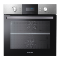
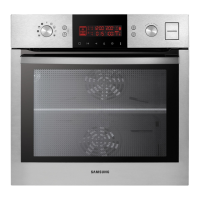
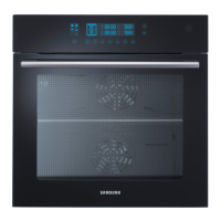
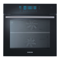
Detailed comparison of features between basic and new models, including oven functions and controls.
Technical specifications such as power source, dimensions, and shipping weight for different oven models.
List of standard accessories provided with the oven, including descriptions, code numbers, and quantities.
Identifies specific tools required for dismantling and reassembling oven components.
Procedure for removing and replacing the upper case and back cover of the oven.
Step-by-step guide for replacing the internal tube, including clamp removal.
Instructions for removing and replacing the entire door assembly from the oven.
Detailed steps for disassembling and replacing the glass panels of the oven door.
Procedures for replacing the rear oven lamp bulb and the side halogen lamp.
Guide for removing and replacing the main control box and its internal components.
Instructions for disassembling and replacing the tube steam module and its related parts.
Detailed steps for removing and replacing the main steam module assembly.
Steps for assembling the main steam module parts, including water tank and generator.
Procedure for replacing the sub-assembly of the steam generator.
Steps for removing and replacing the cooling fan motor.
Procedure for replacing duct covers, brackets, spring ducts, and ceramic filters.
Guide for removing and replacing the convection motor and associated fan components.
Steps for disconnecting and replacing the twin convection heater elements.
Procedure for removing and replacing the partition switch assembly.
Instructions for replacing the thermostat component.
Guide for disconnecting and replacing the terminal block.
Steps for removing and replacing the sensor thermistor.
Procedure for disconnecting and removing the heater grill assembly.
Steps for disconnecting and replacing the bottom heater element.
Guide for removing and replacing the main printed circuit board (PCB) assembly.
Procedure for removing and replacing the door lock assembly.
Explains how to check and interpret error codes displayed by the oven.
Diagnoses and solutions for 'Sensor Open' and 'Sensor Short' errors related to temperature sensors.
Covers various safety-related error codes and their troubleshooting steps.
Troubleshooting flowcharts for sensor open errors (E-27, E-29, E-2b, E-71).
Troubleshooting flowcharts for sensor short errors (E-28, E-2A, E-2C, E-72).
Troubleshooting flowchart for 'Key Short Error' (-SE-).
Troubleshooting flowchart for 'Over Time Error' (S-01).
Troubleshooting flowchart for 'Divider Missing Error' (dE).
Troubleshooting flowchart for 'Cooling Motor Sensor Error' (E-0b).
Troubleshooting flowchart for 'Preheating Error' (E-08).
Troubleshooting flowchart for 'Steam generator temp Error' (E-73).
Troubleshooting flowchart for 'Water Over Supply Error' (E-78).
Diagnosis for abnormal internal oven temperature errors (E-0A, E-09).
Steps to diagnose and resolve power failure issues in the oven.
Guide for troubleshooting 'TCO Open' errors, related to thermal cut-off.
Steps to diagnose and resolve issues related to the main PCB failure.
Procedure for diagnosing and resolving failures in the oven's heating elements.
Visual representation of oven components with numbered labels for identification.
List of main oven components with code numbers, descriptions, specifications, and availability.
List of parts specific to the oven door assembly, including code numbers and descriptions.
List of components related to the oven's control panel and electronics.
List of general or standard parts used in the oven assembly.
Detailed diagram of the main PCB showing connectors, parts, and their functions.
Diagram illustrating the electrical connections and wiring of the steam pyrolytic oven.
Detailed schematic of the power supply, control circuits, and sensor connections.