EasyManua.ls Logo

Samsung CH070EAV1 User Manual

Samsung CH070EAV1
142 pages
To Next Page IconTo Next Page
Page #1 background imageLoading...
Page #1 background image
Refer to the service manual in the GSPN(see the rear cover) for the more information.
AIR CONDITIONERCONTENTS
SYSTEM AIR CONDITIONER
Basic : CH140EAV/UH140GAV
Model
: CH070EAV1/CH090/105/140EAV
UH070EAV1/UH090/105/140EAV
Model Code : CH070EAV1/CH090/105/140EAV
UH070EAV1/UH090/105/140EAV


1. Precautions
2. Product Specifi cations
3. Disassembly and Reassembly
4. Troubleshooting
5. Exploded Views and Parts List
6. PCB Diagram and Parts List
7. Wiring Diagram
8. Schematic Diagram
9. Reference Sheet

Question and Answer IconNeed help?

Do you have a question about the Samsung CH070EAV1 and is the answer not in the manual?

Samsung CH070EAV1 Specifications

General IconGeneral
BrandSamsung
ModelCH070EAV1
CategoryAir Conditioner
LanguageEnglish

Summary

1. Precautions

1-1 Installation Precautions

Guidelines for safe and correct installation procedures.

1-2 Electrical Connection Precautions

Electrical connection and safety requirements for power supply.

1-3 Operational Safety Guidelines

Precautions for safe operation and maintenance during use.

1-4 Disposal and Other Precautions

Environmental guidelines for unit disposal and additional safety tips.

2. Product Specifications

2-1 Product Features

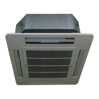
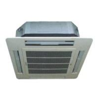
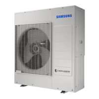
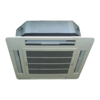
Highlights key features and benefits of the air conditioner.

2-2 Detailed Technical Specifications

Detailed technical specifications for various models.

2-3 Comparative Specifications

Comparison of specifications between different development models.

2-4 Accessories and Options

List and details of accessories and optional parts.

3. Disassembly and Reassembly

3-1 Indoor Unit Procedures

Step-by-step guide for indoor unit disassembly and reassembly.

3-2 Outdoor Unit Procedures

Step-by-step guide for outdoor unit disassembly and reassembly.

4. Troubleshooting

4-1 Indoor Unit Error Display and Check

Interpreting indoor unit LED error codes and troubleshooting steps.

4-2 Outdoor Unit LED Error Display and Check

Interpreting outdoor unit LED error codes and troubleshooting steps.

4-3 Remote Control Option Setup

Procedures for setting optional features via the remote control.

4-4 Initial Checks for Issues

Initial checks for common operational issues and troubleshooting.

4-5 Fault Diagnosis by Symptom

Troubleshooting guides based on specific symptoms or error codes.

5. Exploded Views and Parts List

5-1 Indoor Unit Parts

Exploded view and parts list for the indoor unit components.

5-2 Panel Parts

Exploded view and parts list for the panel assembly.

5-3 Outdoor Unit Parts

Exploded view and parts list for the outdoor unit components.

5-4 Assy Control Out Parts

Exploded view and parts list for the control assembly.

6. PCB Diagram and Parts List

6-1 Block Diagrams of Main PCBs

Visual representations of the main PCB circuit layouts for various units.

6-2 PCB Parts Lists

Comprehensive lists of components for indoor and outdoor unit PCBs.

7. Wiring Diagram

8. Schematic Diagram

8-1 Indoor Unit Schematic

Schematic diagram for the indoor unit's electrical system.

8-2 Outdoor Unit Schematic

Schematic diagram for the outdoor unit's electrical system.

9. Preference Sheet

9-1 Refrigerating Cycle Diagram

Diagram illustrating the refrigerant cycle of the air conditioner.

9-2 Model Name Index

Guide to understanding model codes and their configurations.

Related product manuals