Table 6-4. Misconvergence Tolerances
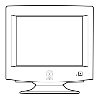
Figure 6-11. Toshiba Magnet Configuration
Figure 6-12. Convergence Measurement Areas
6-4-1 Static (Center) Convergence
Static convergence involves alignment of the red,
blue and green lines in the center area of the
display. See “Dynamic Convergence” for
alignment of the color fields around the edges of
the display.
CONDITIONS
Direction: Monitor facing east
Warm-up: 30 minutes
Display image: Crosshatch pattern
Tolerances: See Table 6-4
PROCEDURE
As shown in Figure 6-11, the CRT used in these
monitors has the same magnet configuration as
shown in Table 6-5 below.
Table 6-5. Magnet Order
Use the following steps to correct any static
misconvergence:
1. Make sure the display is not affected by
external magnetic fields.
2. Locate the pair of 4-pole magnet rings.
3. Unlock the rings and rotate the individual
rings (change the spacing between tabs) to
converge the vertical red and blue lines.
4. Rotate the pair of rings (maintaining the
spacing between tabs) to converge the
horizontal red and blue lines.
6 Alignment and Adjustments
6-8 CKF5607L
6-4 Convergence Adjustments
Misconvergence occurs when one or more of the electron beams in a multibeam CRT fail to meet the
other beams at a specified point.
Position Error in mm CRT Dot Pitch
Center (A) 0.30 0.28
Edge (B) 0.40 0.28
Toshiba CRT
1 Setup Bolt 2 Bow Magnet 3 Spacer 4 2-Pole Magnet
5 Band 6 6-Pole Magnet 7 Spacer 8 4-Pole Magnet
9 Holder 10 Band 11 Tabs
A
B
200 MM
267 MM
CRT Manufacturer Magnet Order from Front of CRT
Toshiba Convergence bow, 2-pole,
6-pole, 4-pole
 Loading...