7 Troubleshooting
CKG7507L 7-5
Check the CN105. Replace the IC102.
Check the 6.3 V line at power supply
circuits (Q605, D620 and Q606).
Power indicator is green
and High voltage is appeared.
Check the High voltage protection
circuits (IC502, L502 and D524).
Does DC 6.3 V appear at
Pin 10 of SK1 on the
Video Socket Board?
Does DC 10 V appear at
Pin 7 of IC502?
Does the video input signal
appear at Pins 5, 8 and 11 of IC101
on the Video PCB Board?
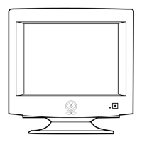
7-6 No Video
Yes
Yes
No
No
Yes
Check signal cable and signal source.
Check IC201 (Pin 37)
on the Main PCB.
No
Yes
No
Does the video output signal
appear at Pins 18, 20 and 23 of
IC101 on the Video PCB Board?
Yes
Does the clamp pulse at Pin
15 of IC101?
Does the contrast DC 2~3 V
appear at Pin 13 of IC101?
No
Check contrast circuis
on the Control PCB and
Main PCB. (VR702,
Q513, etc)
No
30
31
33
No
Does the video amplified pulse
appear at Pins 1, 3 and 5 of
IC102 on the Video PCB Board?
Yes Yes
Does DC 70 V appear at
Pin 6 of IC102?
34
WAVEFORMS
5.40 V (IC101, #15)
CH1 P-P = 5.40 V CH1 RMS = 4.870 V
33
860 mV (IC101, #5, 8, 11)
CH1 P-P = 860 mV CH1 RMS = 2.412 V
30
3.28 V (IC101, #18,20,23)
CH1 P-P = 3.28 V CH1 RMS = 2.748 V
31
40.8 V (IC102, #1, 3, 5)
CH1 P-P = 40.8 V CH1 RMS = 46.28 V
34
 Loading...