Do you have a question about the Samsung CLP-310N and is the answer not in the manual?
General safety guidelines for service engineers and users regarding high voltages, lasers, and replacement parts.
Important safety precautions related to toxic materials, electric shock, and fire hazards.
Guidelines for safely handling the printer, avoiding injury, and preventing damage.
Precautions for disassembling and reassembling printer components, including handling sensitive parts like the OPC drum.
Warnings about high temperatures and rotating parts, and guidelines for moving the printer safely.
Procedures to prevent damage to sensitive electronic components from static electricity.
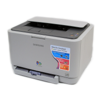
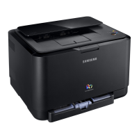
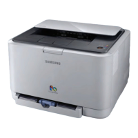
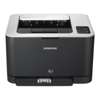
Detailed specifications of the printer, including model, speed, resolution, and memory.
An overview of the printer's features, specifications, and color options.
Detailed technical specifications of the printer's general print engine.
Details about the printer's controller, software, and driver features.
Specifications for the printer's operating environment, including power, noise, temperature, and humidity.
List of accessories included with the printer, such as setup guides, cables, and toner cartridges.
Details on the printer's interfaces, including parallel, USB, network, and user interface elements.
Information on the printer's paper handling capabilities, including capacity, output, duplex, and paper size.
Details about the printer's consumables, including toner cartridges, imaging units, and waste toner.
Information on printer reliability, including monthly duty, SET life cycle, MTBF, and system requirements.
Comparison table of the printer's specifications against other Samsung and HP models.
Overview of the printer's system structure, detailing the main components and their arrangement.
Detailed illustration and description of the main mechanical and electrical parts of the printer.
Explanation of the Electro-photographic (EP) process used in the printer for image formation.
Description of the Main Printed Board Assembly (PBA) and identification of its key components.
Detailed description of the main Printed Circuit Board (PBA) and its controller ICs.
Description of the SMPS (Switching Mode Power Supply) PBA, including AC input and rated output power.
Description of the HVPS (High Voltage Power Supply) PBA, detailing its voltage outputs for various printer functions.
Explanation of the CRUM (Customer Replaceable Unit Monitor) system for tracking consumables and their life.
Overview of the software architecture, showing the interaction between Printer Driver, Language Monitor, and Status Monitor.
Details on the printer's network interface, including its role in communication with the status monitor and printer server.
Flowchart illustrating the printer's firmware (F/W) process, from sensor input to output.
Information on alarm conditions related to toner and transfer belt, and their corresponding actions.
List and explanation of various error statuses the printer can report, including paper jams and cover errors.
Overview of the CRUM system, its function, and the information it stores about consumables.
Procedure for upgrading the printer's firmware (F/W) via USB or network connection.
General precautions for replacing printer parts, including using genuine parts and handling PBAs.
List of parts with limited life and their replacement intervals, including toner, fuser, and transfer unit.
Information on special service parts that should not be disassembled, like LSU and ITB units.
Table listing screws used in the printer, their SEC codes, locations, and quantities for reassembly.
Table detailing harness connections between main board and various units, including PIN and SEC Code.
Step-by-step procedure for removing the printer's covers, including front and top covers.
Procedure for removing the printer's front and top covers.
Procedure for removing the ITB (Image Transfer Belt) unit from the printer.
Procedure for removing the fuser unit, with a caution about its high temperature.
Procedure for removing the HVPS (High Voltage Power Supply) board.
Procedure for removing the Main Printed Board Assembly (PBA).
Procedure for removing the SMPS (Switching Mode Power Supply) board.
Procedure for removing the LSU (Laser Scanning Unit).
Procedure for removing the Holder Pad assembly.
Procedure for removing the Transfer Unit.
Procedure for removing the OPE (Operator Panel) Printed Board Assembly.
Procedure for removing the pick-up roller assembly and rubber.
Information on printer alignment, adjustments, and maintenance procedures.
Details on the printer's functions, including KEY and LED operations.
Explanation of LED functions, behavior, and asserted error operations for status indication.
Tips for avoiding paper jams and procedures for clearing paper jams from the printer.
Information on printing sample patterns for maintenance and diagnosing print quality issues.
Procedure for printing a configuration page to view current printer settings for troubleshooting.
Troubleshooting guide for image defects that appear at regular intervals, identifying faulty rollers.
Guide on using the Engine Diagnostic Control (EDC) mode for checking printer engine operations.
General troubleshooting steps and procedures for resolving printer issues.
Flowchart for diagnosing printer problems based on symptoms and LED status.
A checklist to follow when the printer is not working properly, with suggestions for troubleshooting.
Solutions for common printing problems, such as the printer not printing or not being selected as default.
Troubleshooting steps when the printer fails to feed paper, checking loading and paper specifications.
Troubleshooting steps for slow print jobs, checking job complexity, quality settings, and spooling.
Troubleshooting steps when half the page is blank, checking page orientation and paper size settings.
Troubleshooting steps for recurring paper jams, checking paper loading, type, and debris.
Troubleshooting steps for printing errors where text is wrong, garbled, or incomplete.
Troubleshooting steps for pages printing blank, checking toner, file content, and printer defects.
Troubleshooting for incorrect illustration printing in Windows 98 from Adobe Illustrator.
Troubleshooting steps for poor photo print quality, checking resolution and image size.
Explanation for odd smells during initial printer use, attributed to fuser oil evaporation.
Troubleshooting steps for common print quality issues.
Troubleshooting steps for light or faded prints, checking toner supply and printer cleanliness.
Troubleshooting steps for toner specks on prints, checking paper type and quality.
Troubleshooting steps for dropouts in prints, checking paper condition and toner cartridge.
Troubleshooting steps for vertical lines on prints, checking the imaging unit and printer cleanliness.
Troubleshooting steps for color or black background issues, checking paper weight and printer environment.
Troubleshooting steps for toner smears, checking printer cleanliness, paper, and imaging unit.
Troubleshooting steps for vertical repetitive defects, checking printer cleanliness, toner, and fusing assembly.
Troubleshooting steps for background scatter, checking paper moisture, layout, and print resolution.
Troubleshooting steps for misformed characters, checking paper slickness and printer service needs.
Troubleshooting steps for page skew, ensuring proper paper loading and guide settings.
Troubleshooting steps for paper curl or wave, checking paper loading, quality, and tray orientation.
Troubleshooting steps for paper wrinkles or creases, checking paper loading, quality, and tray orientation.
Troubleshooting steps for dirty printouts, checking for leaking toner and cleaning the printer.
Troubleshooting steps for solid color or black pages, checking toner installation, cartridge, and HVPS.
Troubleshooting steps for loose toner, checking printer cleanliness, paper, and toner cartridge.
Troubleshooting steps for character voids, checking paper surface and specifications.
Troubleshooting steps for horizontal stripes, checking toner installation and cartridge condition.
Troubleshooting steps for paper curl, checking paper loading and tray orientation.
Troubleshooting common error messages and issues encountered when printing from Windows.
Troubleshooting common printing issues specific to Macintosh operating systems and applications.
Troubleshooting common printing issues specific to Linux operating systems and configurations.
Troubleshooting for significant printer problems like lines, voids, and dark images.
Troubleshooting steps for vertical lines and bands on prints, checking developer and transfer rollers.
Troubleshooting steps for vertical white lines, checking for foreign matter in LSU and developer components.
Troubleshooting steps for light images, checking developer roller, ambient temperature, and HVPS output.
Troubleshooting steps for dark or black images, checking charge voltage and HVPS connections.
Troubleshooting steps for background issues, checking toner usage, paper type, and developer life.
Troubleshooting steps for Jam 0 errors, checking solenoids, pads, rollers, and sensors.
Troubleshooting steps for Jam 1 errors, checking SMPS and actuator-feed components.
Troubleshooting steps for multi-feeding issues, checking solenoids, pad friction, and paper surface.
Troubleshooting steps for fuser gear malfunction due to melting, replacing fuser or main board.
Troubleshooting steps for Paper Empty errors, checking paper sensor actuator and engine board.
Troubleshooting steps for Cover Open errors, checking hook lever, connectors, and cover switch.
Troubleshooting steps for defective motor operation causing paper feed issues and Jam 0.
Troubleshooting steps for no power issues, checking power input, SMPS output, and LED panel.
Troubleshooting steps for curved vertical lines during printing, checking +24V supply to LSU.
Troubleshooting steps for LSU errors, checking for foreign matter, main controller defects, or switch harness issues.
Visual index of all exploded view diagrams for printer parts.
Exploded view and parts list for the main internal components of the printer.
Exploded view and parts list for the front cover assembly of the printer.
Exploded view and parts list for the top cover assembly of the printer.
Exploded view and parts list for the rear cover assembly of the printer.
Exploded view and parts list for the Transfer Unit.
Exploded view and parts list for Frame1 assembly.
Exploded view and parts list for Frame2 assembly.
Exploded view and parts list for the Main Drive1 assembly.
Exploded view and parts list for the Main Drive2 assembly.
Exploded view and parts list for the Fuser Unit.
Exploded view and parts list for the Cartridge Transfer Unit.
Exploded view and parts list for the Tank Waste Unit.
Exploded view and parts list for the Cassette assembly.
Block diagram illustrating the overall system architecture and component interactions.
Diagram showing the connections between main board and various units, including pinouts.
Connection diagram between the Main Board and the LSU Unit, detailing pin assignments.
Connection diagram between the SMPS and the Main Board, detailing pin assignments.
Connection diagram between the Main Board and the HVPS, detailing pin assignments.
Connection diagram between the HVPS Board and various sensors, detailing pin assignments.
Connection diagram between the Main Board and the BLDC motor, detailing pin assignments.
Connection diagram between the Main Board and the OPC fusible, detailing pin assignments.
Connection diagrams between the Main Board and various sensors, detailing pin assignments.
Connection diagrams between the Main Board and Crum Joints, detailing pin assignments.
Connection diagrams between the Main Board and actuators (solenoids), detailing pin assignments.
Connection diagrams between the Main Board, SMPS, and Heater Unit/Panel, detailing pin assignments.
List of recommended tools for performing safe and easy troubleshooting of the printer.
Glossary of abbreviations and acronyms used throughout the service manual.
Guidelines for selecting a suitable environment and location for printer installation.
Reproduction of the A4 ISO 19752 standard test pattern for print quality evaluation.
| Color | Yes |
|---|---|
| Duplex printing | No |
| Print technology | Laser |
| Maximum resolution | 2400 x 600 DPI |
| Time to first page (black, normal) | 14 s |
| Time to first page (color, normal) | 26 s |
| Print speed (black, normal quality, A4/US Letter) | 16 ppm |
| Print speed (color, normal quality, A4/US Letter) | 4 ppm |
| Internal memory | 32 MB |
| Maximum internal memory | - MB |
| Sound pressure level (printing) | 47 dB |
| Total input capacity | 150 sheets |
| Total output capacity | 100 sheets |
| Networking features | Ethernet 10 /100 Base TX |
| Compatible operating systems | Windows 2000/ XP/ 2003/ Vista Linux OS Mac OS X 10.3 - 10.5 |
| Maximum duty cycle | 20000 pages per month |
| Maximum print size | 216 x 356 mm |
| Paper tray media types | Envelopes, Glossy paper, Labels, Recycled paper, Transparencies |
| ISO A-series sizes (A0...A9) | A4, A5 |
| Maximum ISO A-series paper size | A4 |
| Power consumption (printing) | - W |
| Display | - |
| Dimensions (WxDxH) | 388 x 313 x 243 mm |
|---|


 Loading...