2 Dedicated Digital Inputs
•
Emergency start/stop
•
See manual for patterns
DMS 2.5 Circuit Details
•
5 channels
•
Maximum 16 systems per channel.
•
Maximum 80 systems
•
Maximum of 128 indoor units and mode
control units (MCU’s) per channel
•
Maximum of 256 indoor units per DMS 2.5
2
3
1
4 5
6
7
8
9
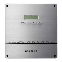
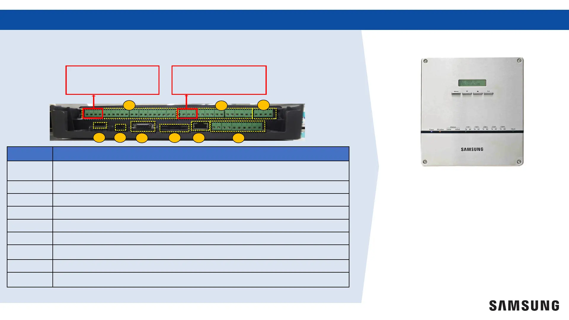
Terminal Block Descriptions
Number
Description
1 Digital Input: (10 channels, fixed addresses)
2 Digital Output: (8 channels, fixed addresses) output voltage = 12VDC, 200mA
3 Reserved: Not used
4 Power: Power supply for DMS 2.5 12VDC, 3.0A (120VAC power adapter provided)
5 Reset Button: Restarts DMS 2.5
6 Reserved: Only used for R&D
7 SD Slot: SD card slot for data storage and updating software (must be formatted FAT32)
8 LAN Port: Ethernet connection to building network for upper-layer devices
9 RS485: Connection for R1/R2 communication to system devices (5 channels)
1
2 Dedicated Digital Outputs
•
Operation on/off
•
Error status