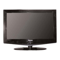
Do you have a question about the Samsung LE32R81BX and is the answer not in the manual?
Essential safety measures to prevent electrical shock and damage, including warnings and hot checks.
Precautions for general servicing, handling electrolytic capacitors, and checking insulation.
Techniques to reduce component damage from static electricity, covering handling and soldering ESD sensitive devices.
Safety guidelines for product installation, including handling, ventilation, and power cord management.
Detailed technical specifications for the LE23R86BD model, covering LCD panel, resolution, power, and environmental considerations.
Detailed technical specifications for the LE26R86BD model, including panel size, resolution, and power consumption.
Detailed technical specifications for the LE32R86BD model, covering display size, resolution, and power consumption.
Technical specifications for the LE32R81B model, detailing panel size, resolution, and operational parameters.
Technical specifications for the LE37R86BD model, including screen size, resolution, and environmental considerations.
Technical specifications for the LE37R81B model, covering display details, resolution, and power.
Technical specifications for the LE40R86BD model, including screen size, resolution, and power consumption.
Technical specifications for the LE40R81B model, detailing panel size, resolution, and environmental conditions.
General instructions for service technicians, emphasizing basic characteristics and test equipment usage.
Procedures for entering factory mode and performing panel checks, including option byte settings.
Lists various factory data items for calibration, service, white balance, and option tables.
Detailed instructions on white balance calibration and adjustment for different input modes.
Procedure for updating the flash ROM using a flash downloader and connecting the necessary cables.
Initial troubleshooting steps involving cable connections, power input, and voltage checks.
Flowcharts for diagnosing specific error modes like No Power, No Video, and No Sound.
Exploded view diagram showing the assembly of the LE23R86BD TV model.
List of parts for the LE23R86BD model, including location, code number, specification, and remarks.
Comprehensive list of electrical parts for the LE23R86BDX model, including location and code numbers.
Detailed list of electrical parts for the LE26R86BDX model, specifying part codes and specifications.
List of electrical parts for the LE40R86BDX model, including location and SA/SNA codes.
Electrical parts list for the LE32R86BDX model, detailing part codes and specifications.
Specifications for the LE37R86BD model, covering LCD panel, scanning frequency, and sound characteristics.
Technical specifications for the LE40R86BD model, such as screen size, resolution, and power consumption.
Detailed wiring diagram for the main board, showing connections for various signals and power inputs.
Pin definitions and characteristics for the main board power supply and speaker connectors.
Schematic diagram illustrating the power supply circuit, including AC input and various voltage outputs.
Schematic diagram for the sound processing section, detailing the audio amplifier and sound blocks.
Schematic diagram showing the input and output jacks, including HDMI, AV, PC, and Component connections.
Schematic diagram for the MICOM (Microcomputer) section, illustrating its connections and functions.
Schematic diagram for the SVP-UX scaler, detailing the ADC and display panel control circuitry.
Schematic diagrams for the DDR memory and Tuner blocks, illustrating their internal connections.
Illustrations and descriptions of the connection panel for various models (LE23-40R86BD).
Instructions for connecting HDMI, DVI, aerial, cable TV, CI card, external AV devices, and computers.
Step-by-step guide for disassembling the monitor, emphasizing safety precautions for sensitive components.
Schematic diagram of the Power Supply Module (SMPS) for 23-inch models.
Schematic diagram of the Power Supply Module (SMPS) for 26-inch and 32-inch models.
Detailed main block diagram showing signal flow and component interactions.
Description and schematic diagrams for the SMPS (Switching Mode Power Supply) board across different models.