EasyManua.ls Logo

Samsung M1711NR - User Manual

Samsung M1711NR
24 pages
Print Icon
To Next Page IconTo Next Page
Loading...
SERVICE
MICROWAVE OVEN CONTENTS
MICROWAVE OVEN
1. Precaution
2. Specifications
3. Operating Instructions
4. Disassembly and Reassembly
5. Alignment and Adjustments
6. Troubleshooting
7. Exploded Views and Parts List
8. Schematic Diagrams
Manual
M1711NR
BWT

Questions and Answers

Summary

PRECAUTIONS TO BE OBSERVED BEFORE AND DURING SERVICING TO AVOID POSSIBLE EXPOSURE TO MICROWAVE ENERGY

1. Precaution

1-1 Safety precautions

Detailed safety measures for servicing to prevent microwave exposure and electrical hazards.

1-2 Special Servicing Precautions

Specific safety rules for technicians during servicing, including tool usage and component handling.

1-3 Special High Voltage Precautions

Critical safety guidelines for handling high voltage components to prevent electrocution.

2. Specifications

2-1 Table of Specifications

Key technical specifications of the microwave oven, including dimensions, power, and frequency.

3. Operating Instructions

3-1 Control Panel

Description of the microwave's control panel layout and functions.

3-2 Features & External Views

Illustrates external features and provides dimensional views of the microwave oven.

4. Disassembly and Reassembly

4-1 Replacement of Magnetron, Motor Assembly and Lamp

Step-by-step guide for removing and replacing key internal components like the magnetron, motor, and lamp.

4-2 Replacement of High Voltage Transformer

Procedure for safely removing and replacing the high voltage transformer, including safety precautions.

4-3 Replacement of Door Assembly

Instructions for disassembling and reassembling the microwave oven door, including specific part removals.

4-4 Replacement of Fuse

Steps for replacing the internal fuse, including checks for related component failures.

4-5 Replacement of Drive Motor

Detailed steps for replacing the drive motor, ensuring correct remounting and connections.

4-6 Replacement of Control Circuit Board

Procedure for accessing and replacing the main control circuit board and associated components.

5. Alignment and Adjustments

5-1 High Voltage Transformer

Procedures for checking continuity and resistance of the high voltage transformer.

5-2 Magnetron

Method for performing continuity checks on the magnetron filament and case.

5-3 High Voltage Capacitor

Steps for checking the continuity and resistance of the high voltage capacitor.

5-4 High Voltage Diode

Instructions for checking the forward and reverse resistance of the high voltage diode.

5-5 Adjustment of Primary Switch, Door Sensing Switch and Monitor Switch

Guide for adjusting and testing interlock and monitor switches for proper door latching and operation.

5-6 Output Power of Magnetron

Method for measuring the magnetron's output power using a water temperature rise test.

5-7 Microwave Heat Distribution - Heat Evenness

Procedure for checking microwave heat distribution uniformity within the oven cavity.

5-8 Procedure for Measurement of Microwave Energy Leakage

Detailed steps for measuring microwave energy leakage using a survey meter and spacer cone.

5-9 Check for Microwave Leakage

Steps to check for microwave leakage near specific components after removing the outer panel.

5-10 Note on Measurement

Important notes and precautions to follow when performing measurement tests.

5-11 Leakage Measuring Procedure

Guidelines for record keeping and notification related to microwave leakage measurements.

6. Troubleshooting

6-1 Electrical Malfunction

Table detailing common electrical issues, their causes, diagnoses, and remedies.

6-1 Electrical Malfunction

Table detailing common electrical issues, their causes, diagnoses, and remedies.

6-2 Unsatisfactory Cooking

Troubleshooting guide for common cooking-related problems, including causes and solutions.

6-3 Part Check List

A list of common parts and symptoms, with check points and recommended remedies.

7. Exploded Views and Parts List

7-1 Exploded Views

Diagrams illustrating the assembly of microwave oven components for identification.

7-2 Main Parts List

A comprehensive list of major parts with their codes, descriptions, specifications, and quantities.

7-3 Control & Door Parts List

Detailed list of parts related to the control panel and door assembly.

7-4 Standard Parts List

List of standard hardware parts such as screws and nuts used in the microwave assembly.

8. Schematic Diagrams

8-1 Schematic Diagrams

Electrical schematics showing the internal wiring and component connections of the microwave oven.

Overview

This document is a service manual for the Samsung M1711NR microwave oven, providing comprehensive information for technicians on its operation, maintenance, and repair.

Function Description:

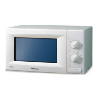
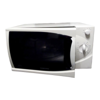
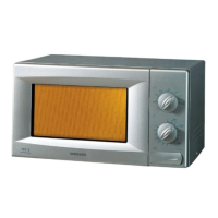
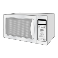
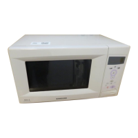
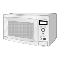
The Samsung M1711NR is a microwave oven designed for cooking and heating food. It utilizes microwave energy to rapidly heat food items, offering various power levels and a timer function for controlled cooking. The oven is equipped with safety features to prevent exposure to excessive microwave energy during operation and servicing.

Important Technical Specifications:

  • Model: M1711NR
  • Timer: 35 minutes
  • Power Source: 230V ~ 50Hz
  • Power Consumption (Microwave): 1,150W
  • Output Power: 100W / 800W (based on IEC-705 TEST PROCEDURE)
  • Operating Frequency: 2,450MHz
  • Magnetron: OM75S(31)
  • Cooling Method: Cooling Fan Motor
  • Outside Dimensions (W x H x D): 489mm x 275mm x 374mm
  • Oven Dimensions (W x H x D): 306mm x 211mm x 320mm
  • Shipping Dimensions (W x H x D): 557mm x 329mm x 451mm
  • Shipping Weight (Approx. NET): 13.5kg
  • High Voltage: 4000 Volts (present at the high voltage area)
  • Fuse Ratings:
    • Cartridge Fuse (M014): 250V, 1.6A, Fast-Acting, CER
    • Cartridge Fuse (M019): 250V, 12A, Slow-Blow, CERAMI
  • Transformer Specifications:
    • Primary Coil Resistance: Approx. 2.5Ω (at 20°C)
    • Secondary Coil Resistance: Approx. 151.5Ω (at 20°C)
    • Filament Resistance: Approx. 0Ω (at 20°C)
  • Capacitor Specifications: Normal continuity for a short time, then indicates 9MΩ. Shorted capacitor shows continuous continuity. Open capacitor shows constant 9MΩ. Resistance between each terminal and chassis should be infinite.
  • Diode Specifications: Infinite resistance in one direction, several hundred KΩ in the other direction (using a meter with 6V, 9V or higher voltage batteries).
  • Microwave Leakage: Maximum allowable leakage is 5mW/cm². Measured leakage must be less than 4mW/cm² after repair or adjustment.

Usage Features:

The microwave oven features a control panel with two main knobs:

  • Variable Cooking Power Control Knob: Allows selection of different power levels (e.g., 100W, 300W, 450W, 600W, 700W, 800W).
  • Timer Knob: Sets the cooking duration up to 35 minutes. 
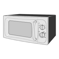
Other external features include:
  • Ventilation Holes: For proper airflow and cooling.
  • Light: Illuminates the oven interior.
  • Door Latches: Securely close the oven door.
  • Open Door Push Button: Releases the door latches to open the door.
  • Safety Interlock Holes: Part of the safety system to prevent microwave emission when the door is open.
  • Turntable, Coupler, and Roller Ring: Ensure even heating of food by rotating the cooking tray.

Maintenance Features:

The service manual provides detailed procedures for various maintenance and repair tasks, emphasizing safety precautions due to high voltages and microwave radiation.

Safety Precautions:

  • General: All repairs must follow procedures in this manual and comply with Federal Performance Standard 21 CFR, Subchapter J(DHHS). Microwave emission checks are mandatory before servicing if the oven is operative. Users must be instructed not to operate the oven with the door open.
  • Microwave Leakage: Notify the Central Service Center if leakage exceeds 5 mW/cm². A leakage check must be performed on each oven before release to the owner.
  • Grounding: All grounds must be checked. The MWO should not be powered from a "2-prong" AC cord. All built-in protective devices must be replaced, and missing protective shields restored.
  • Component Replacement: Use only exact replacement parts, especially for primary and secondary interlock switches, and the interlock monitor switch, to avoid radiation hazards. Never alter or add to the mechanical or electrical design.
  • High Voltage: Always unplug the AC power cord and discharge the high voltage capacitor before touching any components or wiring. Do not attempt to measure high voltages, including magnetron filament voltage. Servicemen should remove watches when working near or replacing the magnetron.
  • ESD: Some semiconductor devices are Electrostatically Sensitive Devices (ESDs). Drain electrostatic charge from your body by touching an earth ground before handling these components.
  • Test Instruments: Connect a test instrument's ground lead to the instrument chassis ground first, and remove it last.

Disassembly and Reassembly Procedures:

  • Magnetron, Motor Assembly, and Lamp Replacement: Involves disconnecting wires, removing covers, screws, and carefully extracting components. Special attention is given to the magnetron antenna and gasket during replacement.
  • High Voltage Transformer Replacement: Requires discharging the capacitor, disconnecting leads, removing mounting bolts, and ensuring correct reconnection.
  • Door Assembly Replacement: Detailed steps for removing and reassembling door components (Door "C", Door "E", Key Door, Spring), with instructions for proper alignment and adjustment to prevent microwave leakage.
  • Fuse Replacement: Involves disconnecting power and replacing the fuse. If the 12A fuse blows due to interlock monitor switch failure, the primary interlock switch, door sensing switch, monitor switch, and power relay must all be replaced simultaneously.
  • Drive Motor Replacement: Steps for removing the glass tray, guide roller, coupler, turning the oven upside down, and replacing the drive motor, ensuring correct remounting and lead connections.
  • Control Circuit Board Replacement: Involves disconnecting connectors, removing screws, and detaching knobs and the timer.

Alignment and Adjustments:

  • High Voltage Transformer Check: Continuity checks for primary, secondary, and filament terminals.
  • Magnetron Check: Continuity checks for open filament or shorted magnetron, and between filament terminal and magnetron case.
  • High Voltage Capacitor Check: Continuity and resistance checks to identify normal, shorted, or open capacitors.
  • High Voltage Diode Check: Resistance measurement in both forward and reverse directions.
  • Primary Switch, Door Sensing Switch, and Monitor Switch Adjustment: Instructions for mounting and adjusting these switches to ensure proper operation and prevent microwave leakage. This includes checking the gap between the switch housing and actuator, and confirming continuity in open and closed door states.

Troubleshooting:

A comprehensive table lists common electrical malfunctions, their causes, diagnostic steps, and remedies. Examples include:

  • Fuse blows out when door is opened: Caused by defective primary interlock switch or interlock monitor switch.
  • Oven lamp does not light: Could be a blown fuse, poor power cord contact, defective lamp, defective timer contacts, or open thermal cutout S/W.
  • Fan motor does not operate: Caused by a defective fan motor or defective timer contacts.
  • Microwave turns off during cooking cycle: Due to too small a load or defective magnetron thermal cutout S/W.
  • Properly shock is felt: Indicates incomplete grounding.
  • Door does not operate properly: Caused by broken door hinges or missing/loose screws.
  • Timer does not operate: Due to a defective timer motor or defective timer S/W contacts.
  • Cooking tray does not rotate: Caused by a defective drive motor or blocked ventilation.
  • Magnetron thermal cutout switch OFF: Due to a defective fan motor, too small a load, or no load.

Unsatisfactory Cooking Troubleshooting:

Another table addresses issues related to unsatisfactory cooking, such as "Food is not heated," detailing causes like open cathode of magnetron, defective H.V. diode, shorted magnetron, poor contact of primary interlock switch, open coil of H.V. transformer, shorted H.V. capacitor, or blown monitor fuse.

Part Check List:

Provides a checklist for diagnosing issues like microwave cooking not working (checking H.V. Transformer, H.V. Capacitor, H.V. Diode) and fan motor not rotating (checking fan motor coil).

Output Power Measurement:

Describes a water temperature rise test using two 1-liter cylindrical borosilicate glass vessels and a glass thermometer to measure the magnetron's output power. The formula for calculation is provided, along with normal temperature rise values.

Microwave Heat Distribution - Heat Evenness:

Outlines a procedure to check heat distribution by measuring water temperature rise in five beakers placed on the cooking tray. The heat distribution rate is calculated as a percentage, which should exceed 65%.

Microwave Energy Leakage Measurement:

Details the procedure for measuring microwave energy leakage using a microwave energy survey meter with a 2-inch spacer cone. It specifies water load, oven operation, meter settings, probe handling, and acceptable leakage levels. Record-keeping and notification procedures for leakage are also included.

Samsung M1711NR Specifications

General IconGeneral
BrandSamsung
ModelM1711NR
CategoryMicrowave Oven
LanguageEnglish

Related product manuals