Alignment and Adjustments
2 Samsung Electronics
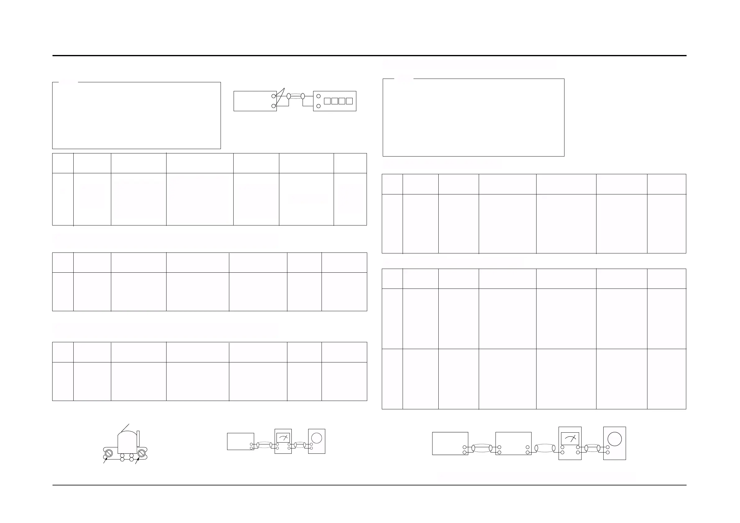
2-1To Adjust Tape Speed
1) Measuring tape: i) MTT-111 (or equivalent)
(Tapes recorded with 3kHz)
ii) MTT-5512 (or equivalent)
iii) MTT-112B (or equivalent)
2) Connect the cassette deck to the frequency counter
as in figure 1-5.
1) Before the actual adjustment, clean the play/recording
head.
2) Measuring tape :
i) MTT-114N(or equivalent 10kHz AZIMUTH control)
ii) MTT-5512
3) The cassette deck is connections as shown in figure 1-7.
Notes
Notes
NOR
SPEED
Control
1
OUT
(connected
to the frequency
counter)
Turn CSVR1
toleft and right
(MAIN PCB)
3KHz±30Hz
Remark
Standard
To Adjust
Pre-Setup
Item
Step
Pre-Setup
Condition
1) Deck 1:MTT-111
2) Press PLAY
SW button
3) Deck 2:Same
as above
AZIMUTH
1
SPK OUT
(VTVM is
connected to
the scope)
- Turn the control
screw to as shown
in Figure 1-6.
Max output
and same phase
(both channels)
After
adjustment
secure it with
REGION
LOCK.
Remark
Standard
To Adjust
Pre-Setup
Item
Step
Pre-Setup
Condition
After putting MTT-
114N into Deck 1
- Press FWD PLAY
button.
AZIMUTH
1
2
SPK OUT
(VTVM is
connected to
the scope)
- Turn the control
screw to as shown
in Figure 1-6.
Max output
and same phase
(both channels)
After
adjustment
secure it with
REGION
LOCK.
6V(±0.5V)
Turn DSVR1,DSVR2
to the right and left
Remark
Standard
To Adjust
Pre-Setup
Item
Step
Pre-Setup
Condition
Fig 1-8
After putting MTT-
114N into Deck 2
1)Press FWD PLAY
button.
After putting MTT-
5512 into Deck 2
1)Press REC PLAY
button.
2)MAIN PCB DCW3,
connectted to VTVM
Recording
Bias
Voltage
2-4 To Adjust PlayBack Level/REC
2. Adjust Deck 2 Play Level/REC BIAS
1. Adjust Deck 1 Play Level
Cassette Deck
output
SPK OUT
Frequency Counter
Figure 1-5
Figure 1-6
SPK OUT
Recording /Play head
AZIMUTH control screw
Figure 1-7
In Out
Cassette Deck
Oscilloscope
2 Cassette Deck
±1%
range
Figure 1-8
Audio OSC.
SET
(MAIN PCB)
Oscilloscope
AUX IN
LINE OUT
VTVM
IN
DCW3
IN OUT
TP
REC
Bias
Voltage
1
Connect to
DCW3 as in
Fig.1-8 and read
the VTVM.
Turn DL4 to the
right and left.
105KHz±0.5KHz
Remark
Standard
To Adjust
Pre-Setup
Item
Step
Pre-Setup
Condition
Input MTT-5512
into Deck2,then
press REC button.
MAIN PCB
2-2. Adjust REC Bias Voltage
L,R
UNBAL-
ANCE
1
Connect to
DCW3 as in
Fig.1-8 and read
the VTVM.
Turn DSVR3 to
the right and left.
±0.5dB
Remark
Standard
To Adjust
Pre-Setup
Item
Step
Pre-Setup
Condition
Input MTT-112B
into Deck2,then
press PLAY button.
MAIN PCB
2-3. Adjust L,R UNBALANCE