EasyManua.ls Logo

Samsung RCD-M30B User Manual

Samsung RCD-M30B
26 pages
To Next Page IconTo Next Page
Page #1 background imageLoading...
Page #1 background image
RADIO CASSETTE RECORDER
CD PLAYER
RCD-M30/30B/30G/35/35G
SERVICE
Manual
RADIO CASSETTE RECORDER CD PLAYER
CONTENTS
Band
RepeatSBS
ON/OFF
Function
CD
T
u
n
i
n
g
V
o
l
u
m
e
M
i
n
M
a
x
Radio
Tape
Radio/
CD OFF
FM
FM
AM
STEREO
MONO
Band
RepeatSBS
ON/OFF
Function
CD
T
u
n
i
n
g
V
o
l
u
m
e
M
i
n
M
a
x
Radio
Tape
Radio/
CD OFF
FM
FM
AM
STEREO
MONO
1. Alignment and Adjustments
2. Disassembly and Reassembly
3. Exploded Views and Parts List
4. Electrical Parts List
5. Block Diagrams
6. PCB Diagrams
7. Wiring Diagram
8. Schematic Diagrams
Question and Answer IconNeed help?

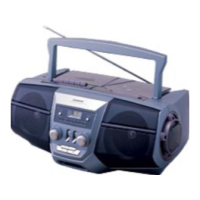
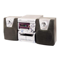
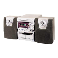
Do you have a question about the Samsung RCD-M30B and is the answer not in the manual?

Samsung RCD-M30B Specifications

General IconGeneral
BrandSamsung
ModelRCD-M30B
CategoryCD Player
LanguageEnglish

Summary

Disassembly and Reassembly

2-1. Front Cabinet Disassembly

Steps for removing the front cabinet and its handle for servicing.

2-2. Top Cabinet Assembly Removal

Instructions for detaching the top cabinet assembly from the main unit.

2-3. Internal Component Removal

Procedures for removing the main PCB, CD mechanism, and cassette mechanism.

Alignment and Adjustments

1-1 Instruction and Pre-Adjustment

Overview of test equipment and pre-adjustment steps for calibration procedures.

1-2-1 FM Adjustment

Detailed FM tuning adjustments and settings for optimal radio reception quality.

1-2-2 AM Adjustment

Detailed AM tuning adjustments for different bands to ensure reception quality.

1-3 Deck Section Adjustments

Procedures for adjusting cassette deck bias, azimuth, and tape speed for optimal performance.

Exploded Views and Parts List

3-1 Cassette Deck Exploded Views

Exploded diagrams and associated parts lists for the cassette deck mechanism.

3-2 Main Unit Exploded Views

Exploded diagrams and associated parts lists for the main unit across various models.

Block Diagram

5-1 Main Block Diagram

Diagram showing the main signal flow and component interconnections of the device.

5-2 CD Part Block Diagram

Diagram detailing the CD player section's functional blocks and signal paths.

Schematic Diagram

8-1 CD Part Schematic

Detailed circuit schematic for the CD player section, showing all components and connections.

8-2 Main Part Schematic

Detailed circuit schematic for the main unit, illustrating complex electrical pathways and components.

Related product manuals