Do you have a question about the Samsung RCD-750 and is the answer not in the manual?
Warnings and specifications related to the laser system, including classifications and beam handling.
Details on pre-shipment safety checks, design warnings, lead dress, and product safety notices.
Guidelines for before, during, and after servicing the unit, including handling parts and wires.
Key precautions for unplugging, avoiding interlocks, using correct parts, and checking insulation.
Step-by-step guide for performing insulation resistance tests on the instrument.
Guidelines for handling ESD-sensitive components to prevent damage from static electricity.
Covers precautions, required tools, and types of chip components for replacement.
Detailed steps for removing and installing various chip components like capacitors, filters, diodes, transistors, and ICs.
Provides overall specifications for the unit, including frequency response, speakers, power, and dimensions.
Details specifications for the tape recorder function, such as frequency response and signal-to-noise ratio.
Lists specifications for the radio tuner, including frequency range and IF.
Provides specifications for the CD player, including frequency range, D/A conversion, and channel separation.
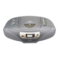
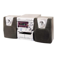
Identifies and labels all controls visible on the front panel of the unit.
Identifies and labels all connectors and switches on the rear panel of the unit.
Step-by-step guide for disassembling the main mounting structure of the unit.
Instructions for removing the front-top panel and its associated components.
Guide for disassembling the back cabinet and related internal assemblies.
Instructions for disassembling the internal chassis and its various PCBs.
Details the segments and their character codes for the LCD display.
Explains CDP block diagram, optical pick-up, RF amplifier, servos, DSP, and D/A converter functions.
Details the pin configuration and functions of the KS 56C220 IC.
Lists pin functions for KA9258D DRIVE and KA9270 AUDIO FILTER ICs.
Details pin functions for the KA9220 ASSP IC.
Details pin functions for the KS9282 DSP IC.
Lists required instruments and key points for radio adjustments.
Details steps for FM frequency coverage and tracking adjustments.
Details steps for adjusting FM/AM IF and coverage/tracking.
Details FM, SW, AM adjustments for frequency coverage and tracking.
Procedures for adjusting tape recording bias, azimuth, and playback speed.
Details focus bias, E.F balance, focus gain, and tracking gain adjustments.
Shows the physical location of adjustment potentiometers on the CD section PCB.
Illustrates the functional blocks and signal flow for the main operational sections of the unit.
Provides an exploded view and part numbers for the main unit components.
Details exploded views and part numbers specific to the cassette deck mechanism.
Provides exploded views and part numbers for the CD player deck mechanism.
Presents the circuit diagram for the main operational sections of the unit.
Shows the circuit diagram specifically for the CD player section.
Illustrates the PCB layout and component markings for the main unit.
Shows the PCB layout and component markings for the tuner section.
Details PCB layouts and markings for the front controls and power supply sections.
Shows the PCB layout and component markings for the CD player section.
Illustrates the internal wiring connections between various sections and components.
Shows internal block diagrams for the KA2293 (FIC1) and TA8207 (AIC401) ICs.
Details the internal block diagram for the KA22291 (JIC) IC.
Shows internal diagrams for the KA9270 (NIC9270) and KA9258 (NIC9258) ICs.
Details the internal block diagram for the KS9282 (NIC9282) DSP IC.
Lists electrical components, their codes, specifications, and quantities for the main section.
Lists electrical components, their codes, specifications, and quantities for the tuner section.
Lists electrical components for the front section.
Lists electrical components for the power section.
Lists electrical components for the CD section.
Lists electrical components for the front part of the CD section.
| Type | CD Player |
|---|---|
| Brand | Samsung |
| Model | RCD-750 |
| Power Consumption | 15W |
| Frequency Response | 20 Hz - 20 kHz |
| Supported Discs | CD-R, CD-RW |
| Outputs | Analog RCA |
| Output Voltage | 2V |