Do you have a question about the Samsung RCD-M30G and is the answer not in the manual?
Steps to remove the front cabinet.
Procedure for detaching the top cabinet assembly.
Instructions for removing main PCB, CD-Mecha, and Cass-Mecha assemblies.
Overview of test equipment and pre-adjustment steps for optimal performance.
FM and AM alignment procedures for the tuner section.
Procedures for recording bias, azimuth, and tape speed adjustments.
Detailed diagrams showing cassette deck components and their assembly.
Comprehensive diagrams of the main unit's internal components and layout.
Comprehensive list of electrical components with specifications and remarks.
Functional block diagram of the main system components and connections.
Block diagram illustrating the CD player section's functional units.
Diagram showing the physical placement of components on the main PCB.
Diagram illustrating the internal wiring and connections between major units.
Detailed schematic of the CD player section's electronic circuitry.
Schematic diagram of the main unit's electronic circuits and components.
| Audio Output | Stereo |
|---|---|
| Bluetooth | No |
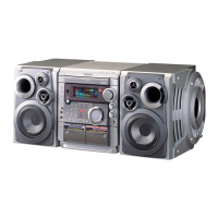
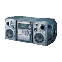
| Dimensions | 230 x 150 x 260 mm (Main Unit) |
| Weight | 3.2 kg (Main Unit) |
| Supported Formats | CD-R, CD-RW |
| Tuner | FM |
| Channels | 2 |