Do you have a question about the Samsung MM-ZS8 and is the answer not in the manual?
Adjustment procedures for the FM tuner section, including THD, Search Level, and IF adjustments.
Steps to adjust the tape speed for the cassette deck, including required measurement tools.
Procedures for adjusting playback level and REC BIAS for both decks of the cassette mechanism.
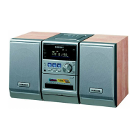
Exploded view and detailed parts list for the cassette deck mechanism.
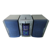
Exploded view illustrating major assemblies of the main audio system unit.
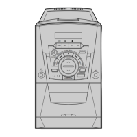
Exploded view and parts list specifically for the speaker unit.
Illustrates the signal flow and component interconnections for the CD playback section.
Comprehensive block diagram showing the overall system architecture and signal paths.
Top and bottom views of the printed circuit board for the CD component.
Top and bottom views of the main printed circuit board assembly.
Printed circuit board layout for the power supply section of the unit.
PCB layouts for the front panel controls and the microphone input sections.
Detailed electronic schematic for the CD playback circuitry.
Comprehensive schematic detailing the main audio system circuitry and interconnections.
Schematics for the tape deck, front panel controls, and microphone sections.
Detailed electronic schematic for the radio tuner circuitry.
| Brand | Samsung |
|---|---|
| Model | MM-ZS8 |
| Category | Stereo System |
| Frequency Response | 20Hz - 20kHz |
| Signal-to-Noise Ratio | 80dB |
| Input Sensitivity | 500mV |