3-9
3. Disassembly and Reassembly
- 이 문서는 삼성전자의 기술 자산으로 승인자만이 사용할 수 있습니다 -
- This Document can not be used without Samsung's authorization -
R530/R730
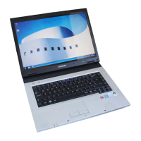
Part Picture Description
Main
System
27. Conditions after removing the RTC.
Front
Cover
Ass’y
28. Remove the ODD sub board.
1) Remove the screw (1 EA) for xing the ODD sub board as
shown in the picture.
(M2 X L4, 1ea)
2) Remove the ODD sub board
29. Remove the USB sub board.
1) Remove the screw (2 EA) for xing the USB sub board as
shown in the picture.
(M2 X L4, 2ea)
2) After removing the USB connector separate the USB
board.
LCD
Ass'y
(15")
30. Remove the LCD module and Front Cover.
1) Remove the screws (2 EA) for xing the both sides of
Hinge as shown in the picture.
 Loading...