Do you have a question about the Samsung RB1855SL and is the answer not in the manual?
Provides essential steps for installing a new refrigerator.
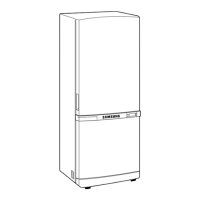
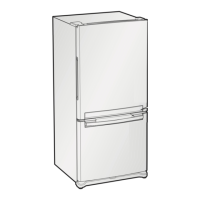
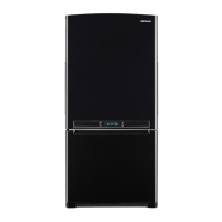
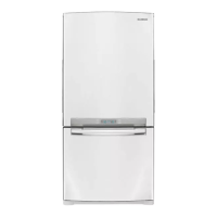
Explains the system used to code refrigerator model numbers and features.
Illustrates the arrangement and removal of interior shelves and bins.
Details the external dimensions (W x D x H) of the refrigerator models.
Details the path of refrigerant through the cooling cycle components.
Illustrates how cold air is distributed throughout the appliance.
Step-by-step guide for removing the control panel unit.
Instructions for replacing the internal refrigerator lamp safely.
Instructions for replacing the internal freezer lamp safely.
Steps to access and remove the evaporator cover in the refrigerator section.
Steps to access and remove the evaporator cover in the freezer section.
Procedure for removing and replacing the refrigerator evaporator assembly.
Procedure for removing and replacing the freezer evaporator assembly.
Guidance on accessing the main electrical components and machinery.
Explains the design and interaction of the appliance's display panel.
Comprehensive guide to setting and adjusting refrigerator and freezer temperatures.
Details features like Quick Freeze, Quick Cool, and Sabbath mode.
Covers buzzer alarms and the automatic defrost cycle functionality.
Information on using built-in tests and self-diagnostics for troubleshooting.
Explains how the appliance shows actual versus set temperatures.
Explains the fundamental electronic circuits for power and system initialization.
Details the circuits for temperature sensors and door switches.
Covers the circuits responsible for user interface and component operation.
Information on customizing settings via PCB diodes.
Steps to diagnose issues when the unit does not power on.
Diagnostic flows for various sensors and internal components.
Steps to diagnose problems with the compressor and cooling fans.
Diagnostic procedures for defrost cycle failures and alarms.
Steps to diagnose issues with the digital panel and interior lighting.
Illustrated parts list for the freezer section.
Illustrated parts list for the refrigerator section.
Illustrated parts lists for the refrigerator door and cabinet components.
Information on connector pinouts and procedures for testing relays.
Methods for testing system loads and measuring sensor resistance.
Guidance on testing door switches and activating test modes.
Data table correlating temperature, resistance, and voltage for sensors.
| Ice Maker | No |
|---|---|
| Ice Tray | Yes |
| Door Lock | No |
| Color | Silver |
| Shelves | 3 Glass Shelves |