Do you have a question about the Samsung RB2055SW and is the answer not in the manual?
Provides essential safety precautions for service personnel handling appliance repair.
Details the various shelves and bins within the refrigerator and freezer compartments.
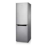
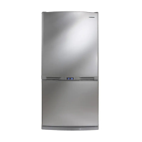
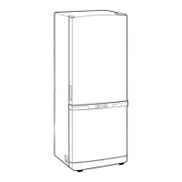
Provides specific external dimensions of the refrigerator models in millimeters.
Illustrates the path refrigerant takes through the cooling system.
Diagrams how cold air is circulated within the refrigerator and freezer.
Step-by-step guide for disassembling the refrigerator's control panel.
Procedure for removing and replacing the refrigerator compartment light.
Procedure for removing and replacing the freezer compartment light.
Instructions for removing the evaporator cover in the refrigerator section.
Instructions for removing the evaporator cover in the freezer section.
Guide on how to remove the evaporator from the refrigerator.
Guide on how to remove the evaporator from the freezer.
Steps for accessing and disassembling the machine compartment and electric box.
Explains the interactive display layout and features of the appliance.
Details how to set and adjust temperatures for freezer and refrigerator compartments.
Describes the functions and triggers for the appliance's buzzer alarms.
Explains the automatic defrost cycle operation and timing.
Outlines the procedure for using the test functions for product inspection.
Describes the appliance's behavior and self-test sequence upon initial power-up.
Explains how the appliance recovers and maintains settings after a power interruption.
Details the process and indicators for the appliance's self-diagnostic testing.
Describes how the display shows the status of currently operating components.
Explains how actual and set temperatures are displayed under various conditions.
Details the power supply circuit, including voltage regulators and distribution.
Describes the oscillator circuit responsible for clock generation and timing.
Explains the function of the reset circuit in initializing the appliance's system.
Details the circuit for door switches and their interaction with the main control.
Describes the temperature sensors and their input to the control system.
Explains how button inputs are scanned and displayed on the appliance interface.
Describes how various loads like compressor and heaters are controlled.
Covers adjustable temperature settings and other optional functions via PCB diodes.
Troubleshooting flowchart for when the appliance does not power on.
Guides for diagnosing issues indicated by the appliance's self-diagnosis system.
Troubleshooting steps for a compressor that is not operating correctly.
Diagnostic procedures for when the freezer cooling fan fails to operate.
Diagnostic procedures for when the refrigerator cooling fan fails to operate.
Troubleshooting for the compressor cooling fan motor not functioning.
Troubleshooting steps for the appliance failing to perform the defrost cycle.
Diagnostic steps for resolving continuous alarm or beep issues.
Catalog of all parts specific to the freezer compartment with part numbers.
Catalog of all parts specific to the refrigerator compartment with part numbers.
Illustrated parts list for the refrigerator door components.
Catalog of cabinet parts and external components with part numbers.
Diagram showing wire connections on the main PCB and cabinet door.
Procedure for checking relay operation and continuity for failure diagnosis.
Methodology for testing various loads like fans and heaters for proper function.
Instructions on how to measure resistance of temperature and defrost sensors.
Guidance on testing door switches and their signals to the control unit.
Explains the use of test buttons for forced compressor and defrost operations.
A table correlating temperature sensor resistance and voltage readings.
| Category | Refrigerator |
|---|---|
| Color | White |
| Energy Star Certified | No |
| Energy Rating | A+ |
| Noise Level | 42 dB |
| Type | Freestanding |